Large effective area high SBS threshold optical fiber

a high-sbs threshold, optical fiber technology, applied in the direction of cladded optical fiber, optical elements, instruments, etc., can solve the problems of nonlinear penalty, inability to reflect back undetected large amount of signal power, and stimulated brillouin scattering (sbs) to achieve the effect of suitable performan

Active Publication Date: 2005-10-04
CORNING INC
View PDF40 Cites 57 Cited by
  • Summary
  • Abstract
  • Description
  • Claims
  • Application Information

AI Technical Summary

Benefits of technology

[0039]Preferably the optical fiber described and disclosed herein allows suitable performance at a plurality of operating wavelength windows between about 1260 nm and about 1650 nm. More preferably, the optical fiber described and disclosed herein allows suitable performance at a plurality of wavelengths from about 1260 nm to about 1650 nm. In a preferred embodiment, the optical fiber described and disclosed herein is a dual window fiber which can accommodate operation in at least the 1310 nm window and the 1550 nm window.

Problems solved by technology

Stimulated Brillouin Scattering (SBS) is a dominant nonlinear penalty in many optical transmission systems.
An undesirably large amount of the signal power can thus be reflected back toward the transmitter due to SBS.
In addition, the scattering process increases the noise level at the signal wavelength.
The combination of decrease in signal power and increase in the noise both lower the SNR and lead to performance degradation.
The change in pressure causes material density to change, thereby resulting in refractive index fluctuations.
Above the SBS threshold of an optical fiber, the number of stimulated photons is very high, resulting in a strong reflected field which limits the optical power that is transmitted and which reduces the SNR.

Method used


Image

  • Large effective area high SBS threshold optical fiber
  • Large effective area high SBS threshold optical fiber
  • Large effective area high SBS threshold optical fiber

Examples


Embodiment Construction

[0056]Additional features and advantages of the invention will be set forth in the detailed description which follows and will be apparent to those skilled in the art from the description or recognized by practicing the invention as described in the following description together with the claims and appended drawings.

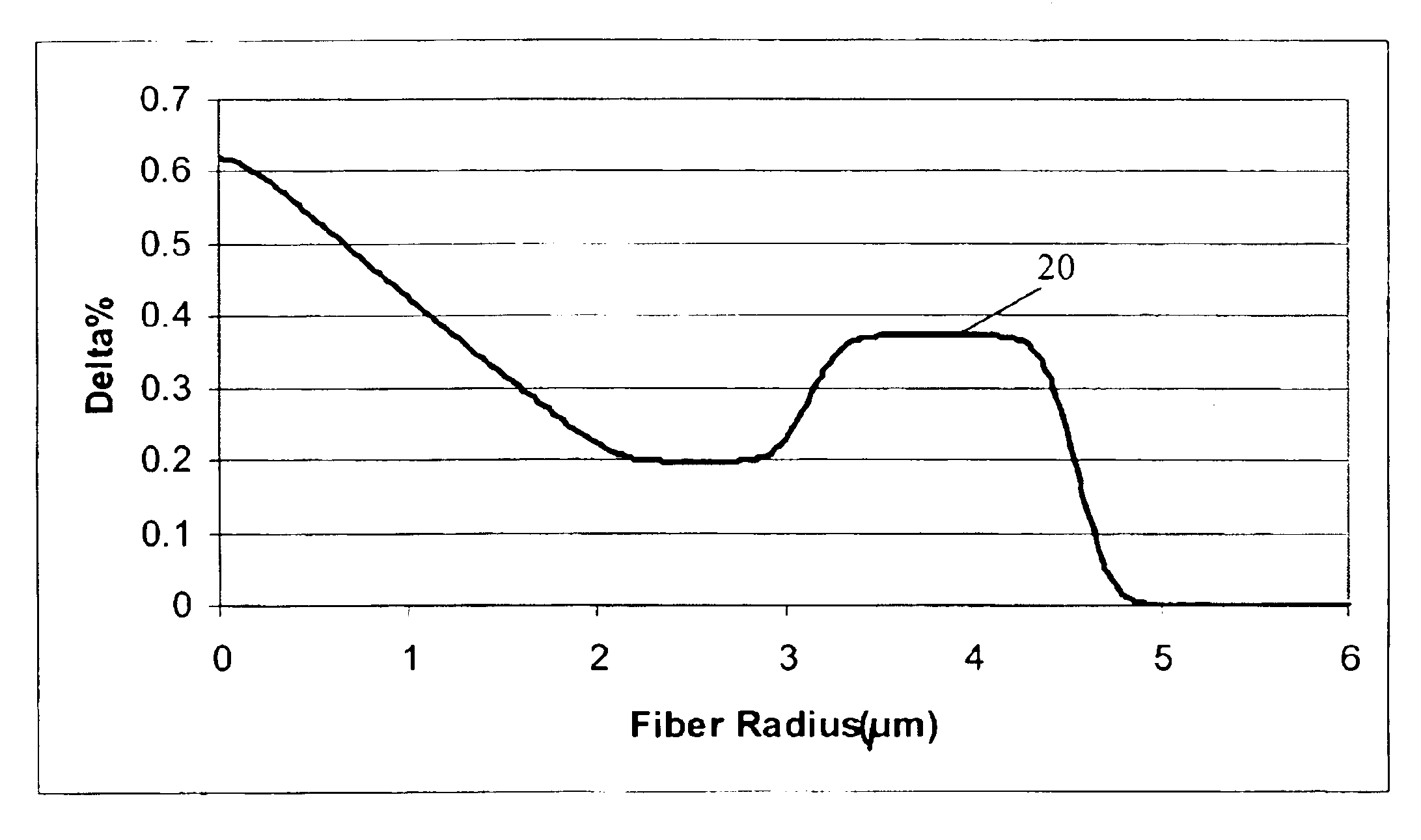
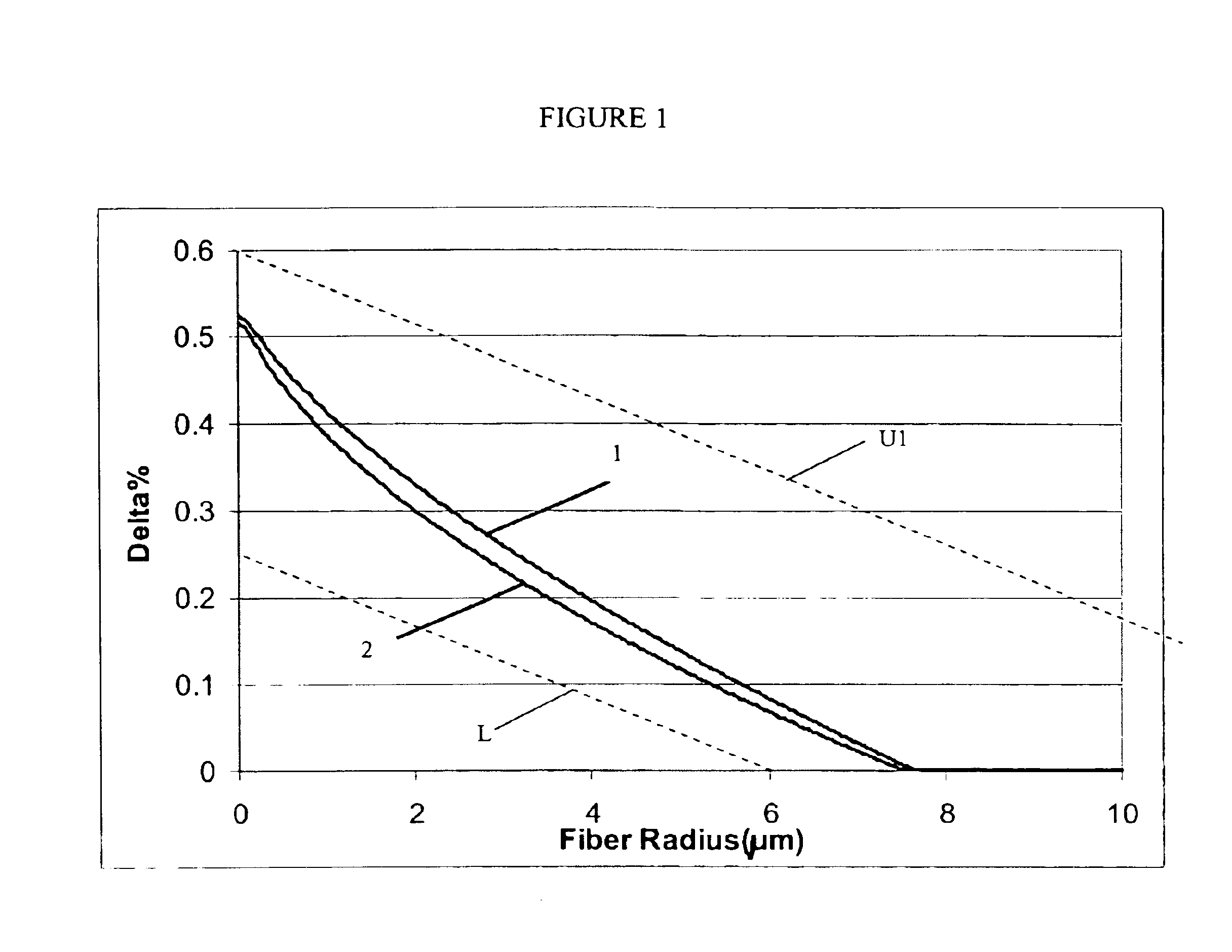
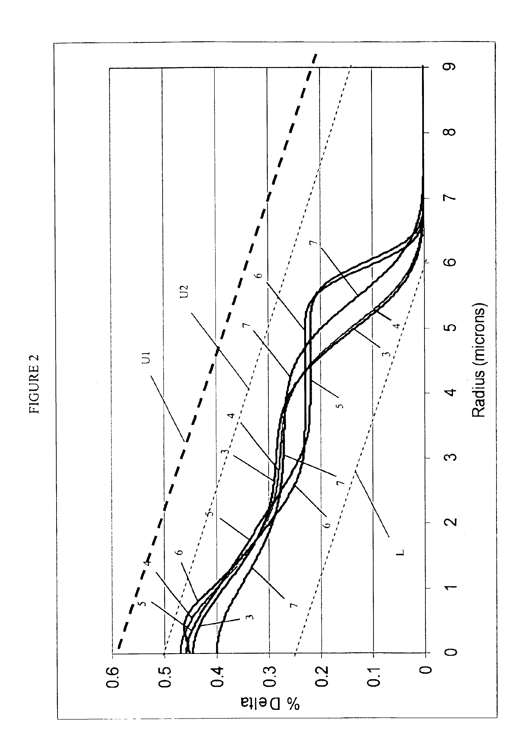
[0057]The “refractive index profile” is the relationship between refractive index or relative refractive index and waveguide fiber radius.

[0058]The “relative refractive index percent” is defined as Δ% =100×(ni2−nc2) / 2ni2, where ni is the maximum refractive index in region i, unless otherwise specified, and nc is the average refractive index of the cladding region. As used herein, the relative refractive index is represented by Δ and its values are given in units of “%”, unless otherwise specified. In cases where the refractive index of a region is less than the average refractive index of the cladding region, the relative index percent is negative and is referred to as...


PUM


Abstract

An optical waveguide fiber having a high threshold for stimulated Brillouin scattering. The optical fiber preferably has large optical effective area, and further preferably has a low zero dispersion wavelength.

Description

CROSS-REFERENCE TO RELATED APPLICATIONS[0001]This application claims the benefit of priority under 35 U.S.C. § 119(e) of U.S. Provisional Application Ser. No. 60 / 467,676 filed May 2, 2003; U.S. Provisional Application Ser. No. 60 / 507,313 filed Sep. 29, 2003; U.S. Provisional Ser. No. 60 / 528,953 filed Dec. 11, 2003; and U.S. Provisional Application Ser. No. 60 / 546,490 filed Feb. 20, 2004.BACKGROUND OF THE INVENTION[0002]1. Field of the Invention[0003]The present invention relates to high SBS threshold optical fibers. More preferably, the present invention relates to high SBS threshold optical fibers having large effective area.[0004]2. Technical Background[0005]Stimulated Brillouin Scattering (SBS) is a dominant nonlinear penalty in many optical transmission systems. In many systems, the launching of large power to optical fiber while maintaining high signal to noise ratio (SNR) is desirable. However, as the launch power or signal power of an incident signal launched into an optical ...

Claims


Application Information

Patent Timeline
Patent Type & Authority Patents(United States)
IPC IPC(8): G02B6/036G02B6/028G02B6/02H01S3/30
CPCG02B6/02014G02B6/02242G02B6/02266G02B6/03633G02B6/03638G02B6/03644G02B6/03666G02B6/03611G02B6/29377H01S3/302G02B6/02G02B6/028
Inventor BICKHAM, SCOTT R.CHOWDHURY, DIPAKBIN Q.HOWARD, MADISON L.KUMAR, SHIVAMA, DAIPINGMISHRA, SNIGDHARAJ K.RUFFIN, A. BOHTEN, SERGEY Y.
Owner CORNING INC
Why Eureka
Try Eureka