Defibrillation pacing circuitry

a technology of pacing circuit and defibrillation, which is applied in the direction of heart stimulators, therapy, heart defibrillators, etc., can solve the problems of not having a practical use, system is far more complicated to use, and has never been used

Inactive Publication Date: 2005-10-04
CAMERON HEALTH
View PDF62 Cites 131 Cited by
  • Summary
  • Abstract
  • Description
  • Claims
  • Application Information

AI Technical Summary

Benefits of technology

[0014]Accordingly, the invention relates in various aspects to methods and apparatus for selectively converting a defibrillator circuit or circ...

Problems solved by technology

This system is far more complicated to use than current ICD systems using transvenous lead systems together with an active can electrode and therefore it has no practical use.
It has in fact never been used because of the surgical difficulty of applying such a device (3 incisions), the impractical abdominal location of the generator and the electrically poor sensing and defibrillation aspects of such a system.
ICDs are very effective at treating V-Fib, but are therapies that still require significant surgery.
In addition, chronic transvenous lead systems, their reimplantation and removals, can damage major cardiovascular venous systems and the tricuspid valve, as well as result in life threatening perforations of the great vessels and heart.
Consequently, use of transvenous le...

Method used


Image

  • Defibrillation pacing circuitry
  • Defibrillation pacing circuitry
  • Defibrillation pacing circuitry

Examples


Embodiment Construction

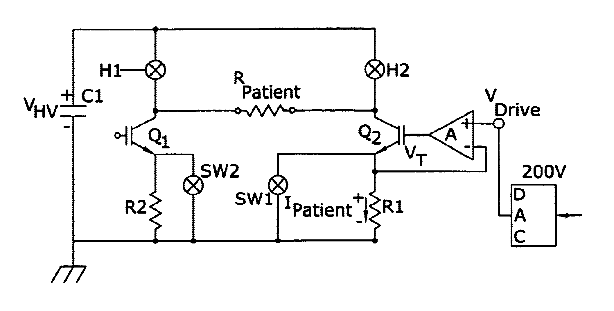
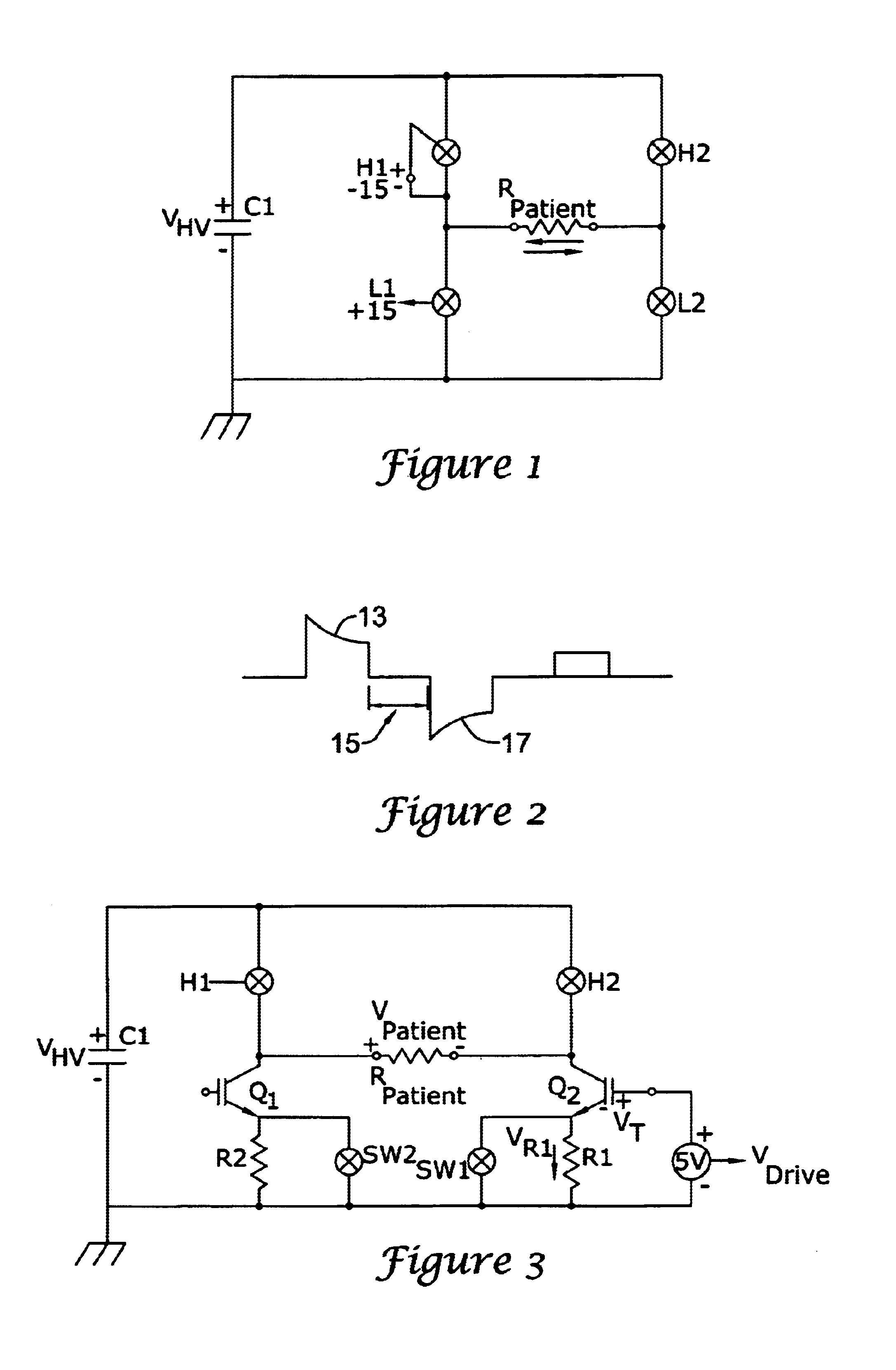
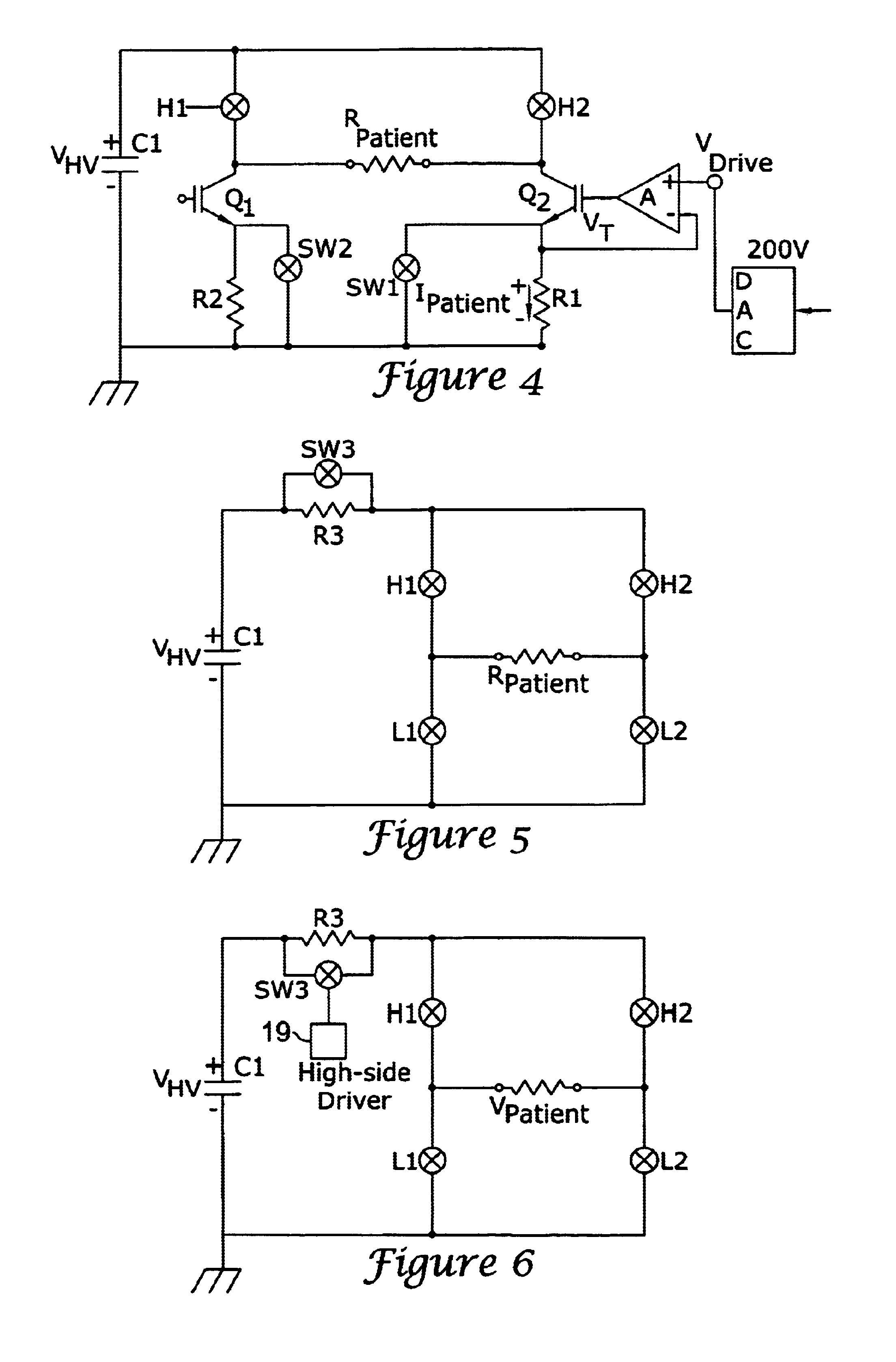
[0022]FIG. 1 illustrates a conventional “H-bridge” defibrillator circuit 11. The circuit 11 includes a capacitor C1 which is charged to a high voltage VHV and four switches H1, H2, L1, L2. The capacitor C1 and switches H1, H2, L1, L2 are used to create either a monophasic voltage pulse or a biphasic voltage pulse (FIG. 2) across a patient represented by resistance RPATIENT. In various applications, the switches H1, H2, L1, L2, may be MOSFETs, IGBTs, or SCRs (silicon controlled rectifiers).

[0023]To create a biphasic waveform such as that shown in FIG. 2, a first pair of switches, e.g., H1 and L2, may be closed to create a positive pulse 13. Then all of the switches, H1, H2, L1, L2, are turned off during a “center pulse” delay period 15. At the end of the delay period 15, the switches H2 and L1 are both closed, thereby reversing the current through the patient RPATIENT to produce a negative voltage pulse 17. Typically, digital logic is employed to control the sequencing of the switche...


PUM


Abstract

Electrical circuit componentry is switchable into a defibrillator circuit to deliver a constant pacing current to a patient. The circuitry may include a constant current source inserted in a leg of the defibrillator circuit or a resistor of selected value inserted between a high voltage source and the high side of a defibrillator circuit.

Description

CROSS-REFERENCE TO RELATED APPLICATIONS[0001]The invention of the present application may find application in systems such as are disclosed in U.S. patent application entitled “SUBCUTANEOUS ONLY IMPLANTABLE CARDIOVERTER-DEFIBRILLATOR AND OPTIONAL PACER,” having Ser. No. 09 / 663,607, filed Sep. 18, 2000, now U.S. Pat. No. 6,721,597, and U.S. patent application entitled “UNITARY SUBCUTANEOUS ONLY IMPLANTABLE CARDIOVERTER-DEFIBRILLATOR AND OPTIONAL PACER,” having Ser. No. 09 / 663,606, filed Sep. 18, 2000, now U.S. Pat. No. 6,647,292, of which both applications are assigned to the assignee of the present application, and the disclosures of both applications are hereby incorporated by reference.[0002]In addition, the foregoing applications are related to the U.S. patent application Ser. No. 09 / 940,283 and entitled “DUCKBILL-SHAPED IMPLANTABLE CARDIOVERTER-DEFIBRILLATOR CANISTER AND METHOD OF USE,” U.S. patent application Ser. No. 09 / 940,371 and entitled “CERAMICS AND / OR OTHER MATERIAL INSU...

Claims


Application Information

Patent Timeline
IPC IPC(8): A61N1/39
CPCA61N1/39A61N1/3912A61N1/3962A61N1/362A61N1/39622
Inventor OSTROFF, ALAN H.
Owner CAMERON HEALTH
Why Eureka
Try Eureka