Radiofrequency thermal balloon catheter

a radiofrequency thermal and catheter technology, applied in the field of radiofrequency thermal balloon catheters, can solve the problems of uneven distribution of temperature in the balloon, inability to uniformly heat the tissues in contact with the balloon, and inability to uniformly heat the tissues

Active Publication Date: 2005-10-04
JAPAN ELECTEL
View PDF12 Cites 203 Cited by
  • Summary
  • Abstract
  • Description
  • Claims
  • Application Information

AI Technical Summary

Benefits of technology

[0005]Accordingly, it is an object of the present invention to solve those problems in the prior art and to provide a radiofrequency thermal balloon catheter capab

Problems solved by technology

However, electrode lines forming the electrode cannot be uniformly arranged in the balloon.
Consequently, the temperature is distributed

Method used


Image

  • Radiofrequency thermal balloon catheter
  • Radiofrequency thermal balloon catheter
  • Radiofrequency thermal balloon catheter

Examples


first embodiment

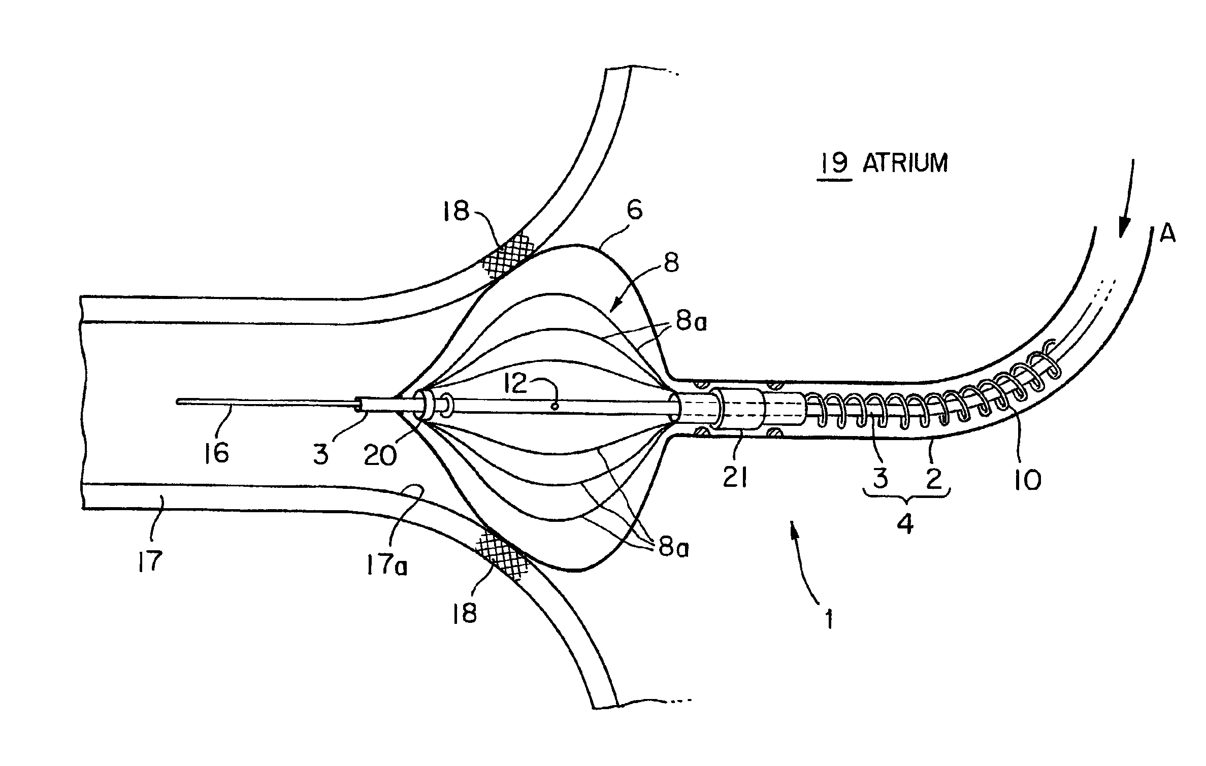
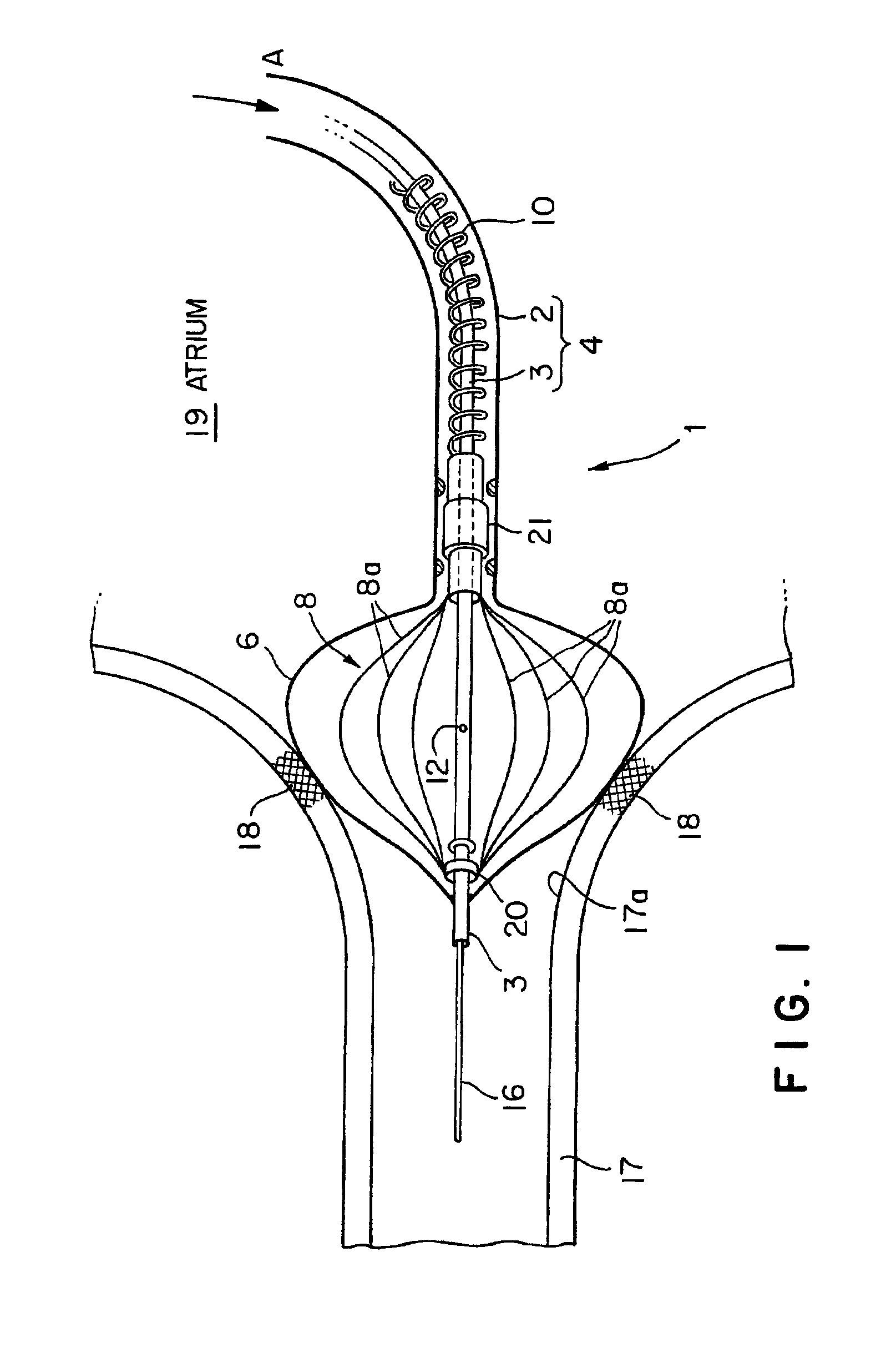
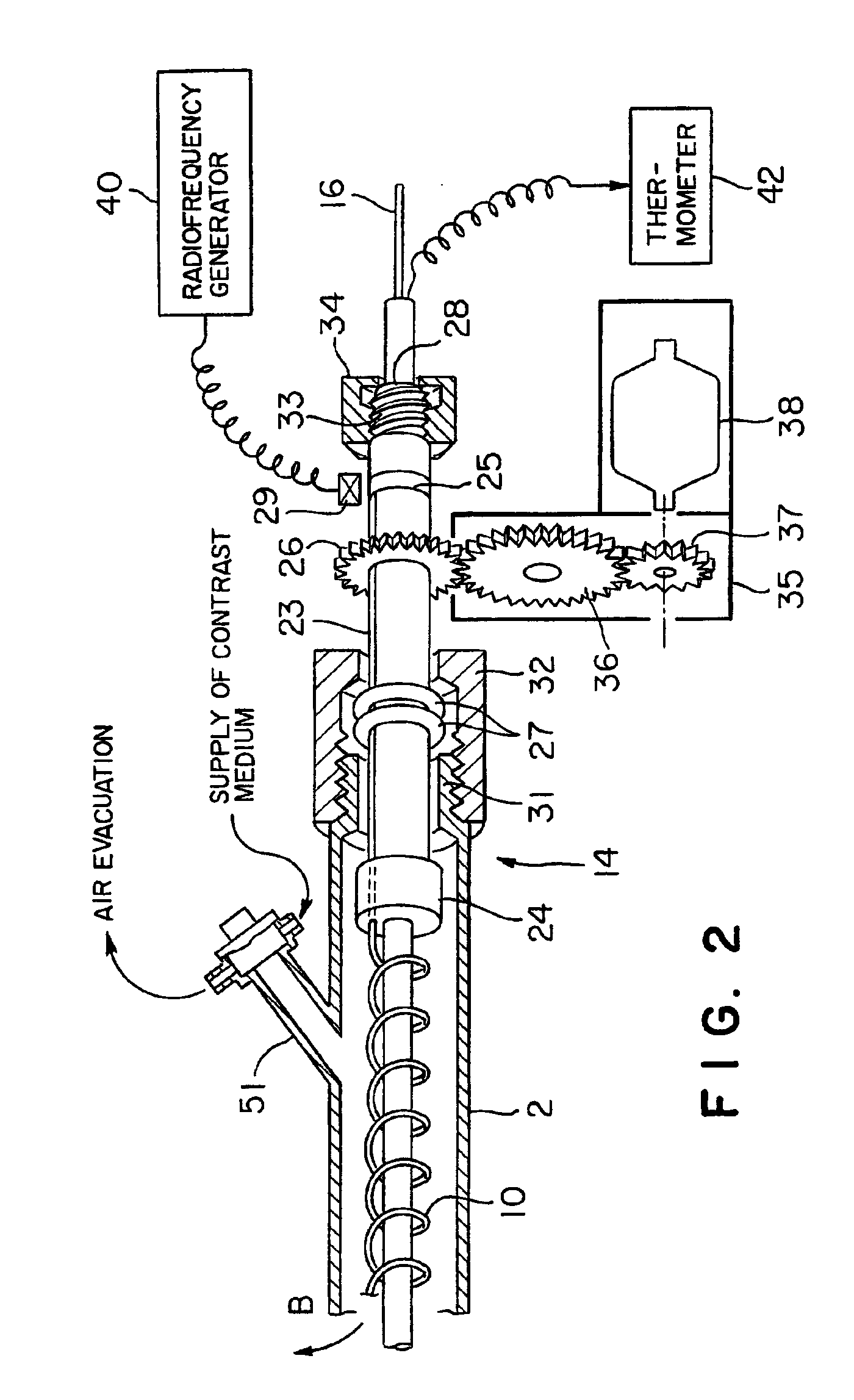
[0039]A radiofrequency thermal balloon catheter in a first embodiment according to the present invention will be described with reference to FIGS. 1 to 4. Referring to FIGS. 1 and 2, a radiofrequency thermal balloon catheter 1 includes a catheter 4 consisting of an outer shaft 2 and an inner shaft 3 extended in the outer shaft 2 so as to be slidable relative to the outer shaft 2, an inflatable balloon 6 capable of being inflated so as to be in contact with a target lesion and extended between respective end parts of the outer shaft 2 and the inner shaft 3, a radiofrequency electrode 8 disposed in the balloon 6, a lead wire 10 electrically connected to the radiofrequency electrode 8, a thermocouple 12 placed in the balloon 6 and capable of sensing temperature in the balloon 6, and a stirring device 14, i.e., a temperature distribution uniformizing means, for uniformizing temperature distribution in a liquid contained in the balloon 6. A guide wire 16 is extended through the inner sha...

third embodiment

[0071]Referring to FIG. 8 showing a radiofrequency thermal balloon catheter 1 in a third embodiment according to the present invention, the radiofrequency thermal balloon catheter 1 includes a balloon 6 and a stirring device 80 for stirring a liquid contained in the balloon 6 to uniformize temperature distribution in the liquid.

[0072]The stirring device 80 includes a connecting pipe 82 connected to an outer shaft 2 so as to open into an annular passage 83 defined by the outer shaft 2 and an inner shaft 3 extended through the outer shaft 2, and a vibration generator 81, such as a vibration-generating diaphragmatic pump, to apply vibrations to a liquid filling up the annular passage 83. The connecting pipe 82 communicates with the balloon 6 by means of the annular passage 83. Vibrations 86 of, for example, about 1 Hz generated by the vibration generator 81 propagate through the liquid filling up the connecting pipe 82 and the annular passage 83. Consequently, eddies 85 are produced in...


PUM


Abstract

A radiofrequency thermal balloon catheter uniformly heats tissues in contact with the balloon to achieve thermotherapy such as ablation or hyperthermia safely and properly for a diseased part. The radiofrequency thermal balloon catheter includes a catheter (4) having an outer shaft (2) and an inner shaft 3 extended through the outer shaft so as to be slidable relative to the outer shaft, an inflatable balloon (6) capable of being inflated so as to be in contact with a target lesion (18) and provided between respective front end parts of the outer and the inner shaft, and a radiofrequency electrode (8) extended in a wall of the balloon or inside the balloon to be used for radiofrequency energy supply in combination with a counter electrode (53). The counter electrode is disposed at a predetermined position, for example, inside the balloon, in the wall of the balloon, in a position neighboring the balloon or on the patient's body surface. A lead wire (10) electrically connects to the radiofrequency electrode. A temperature sensor (12) is capable of sensing temperature of a liquid contained in the balloon. A temperature distribution uniformizing device (14) uniformizes the temperature distribution in the liquid contained in the balloon.

Description

BACKRGROUND OF THE INVENTION[0001]1. Field of the Invention[0002]The present invention relates to a radiofrequency thermal balloon catheter (RTBC) and, more particularly, to a radiofrequency thermal balloon catheter for the treatment of cardiovascular disease.[0003]2. Description of the Related Art[0004]Therapeutic methods using an inflatable balloon, and an electrode placed in the balloon, and capable of creating a radiofrequency electric field by supplying radiofrequency energy to the electrode to heat the tissues in contact with the balloon for therapy, are disclosed in, for example, Japanese Patent Nos., 2538375, 2510428 and 2574119 granted to the applicant of the present invention. The tissues in contact with the balloon must be uniformly or homogeneously heated to achieve the therapy satisfactorily. However, electrode lines forming the electrode cannot be uniformly arranged in the balloon. If the lines of the electrode are irregularly arranged, a liquid contained in the balloo...

Claims


Application Information

Patent Timeline
IPC IPC(8): A61B18/08A61B18/04A61N1/06A61B18/12A61F7/08A61M25/00A61N1/40
CPCA61B18/1492A61B2017/00084A61B2018/00208A61B2018/00214A61B2018/00267A61B2018/00422A61B2018/00821A61B2018/0022
Inventor SATAKE, SHUTARO
Owner JAPAN ELECTEL
Why Eureka
Try Eureka