
Method and apparatus for vaporizing fuel for a reformer fuel cell system

a fuel cell and reformer technology, applied in lighting and heating equipment, electrochemical generators, fire-box steam boilers, etc., can solve the problems of bulk reduction of the load carrying capacity of the vehicle, reducing the overall fuel efficiency of the vehicle, and affecting the efficiency of the fuel cell system

Inactive Publication Date: 2005-10-11
MODINE MFG CO +1
View PDF19 Cites 34 Cited by
  • Summary
  • Abstract
  • Description
  • Claims
  • Application Information

AI Technical Summary

Benefits of technology

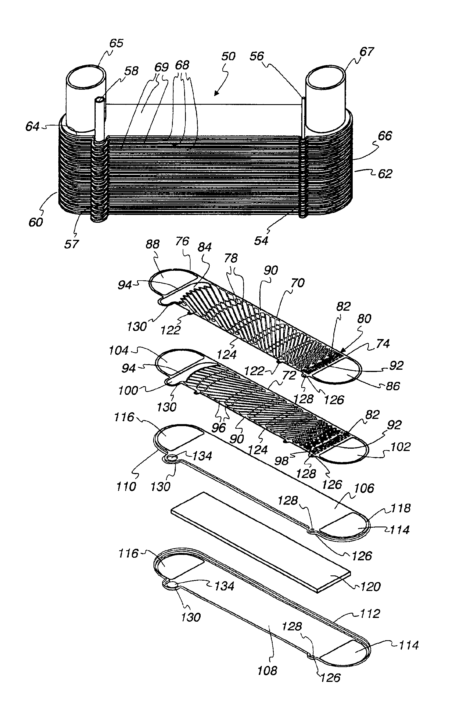
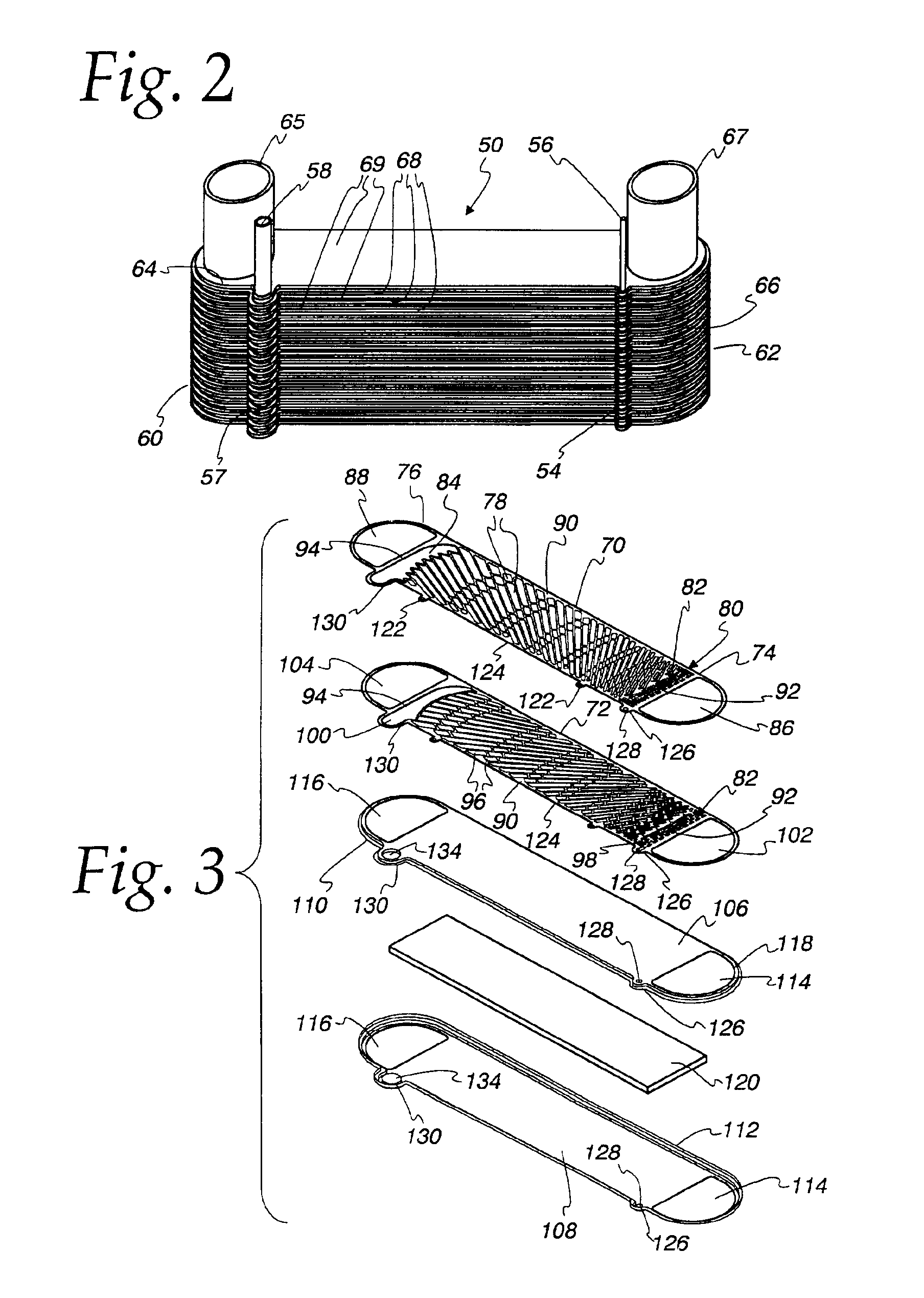
The invention is a new and improved fuel cell system that includes a fuel vaporizer for vaporizing liquid fuel for use in the fuel cell system. The fuel vaporizer includes a heat exchanger with alternating hot fluid passages and liquid / vaporized fuel passages, which are in heat exchange relation with each other. The hot fluid passages each include a fin or fins and two separator plates, which are bonded to and sandwich the fin(s). The fuel vaporizer also includes a liquid fuel inlet and a vaporized fuel outlet with the liquid / vaporized fuel passages extending between them and including two abutting plates, each having elongated slots therein which extend diagonally to the mean direction of fuel flow in the liquid / vaporized fuel passages with the slots in one plate criss-crossing the slots in the other plate to be in fluid communication therewith. The technical effect of the invention is to provide a more efficient and effective fuel cell system with improved fuel vaporization and pressure drop capabilities.

Problems solved by technology

While for many non-vehicular applications, the matter of vaporizing the water and the fuel may be handled relatively simply, the problem is much more difficult where the production of electricity by the fuel cell is expected to respond rapidly to a change in electrical load.
Bulk and weight are highly disadvantageous in that weight reduces the overall fuel efficiency of the vehicle and bulk reduces the load carrying capacity of the vehicle to the point that it is impractical to provide a vehicle that can compete with conventionally powered vehicles in use today.

Method used


Image

  • Method and apparatus for vaporizing fuel for a reformer fuel cell system
  • Method and apparatus for vaporizing fuel for a reformer fuel cell system
  • Method and apparatus for vaporizing fuel for a reformer fuel cell system

Examples


Embodiment Construction

[0044]Exemplary embodiments of the invention will be described herein in the environment of intended use in a vehicle and one which utilizes methanol as a hydrogen containing liquid that is combined with water to produce a hydrogen rich gas for use in a fuel cell. Methanol is a preferred fuel because it is easy to reform into the anode gas. However, it is to be understood that the invention may be employed with efficacy in non-vehicular applications, particularly where rapid response to a load change is required. The vaporizer may also be employed with efficacy in other reformer type fuel cell systems that employ a liquid fuel other than methanol as, for example, ethanol, gasoline, diesel fuel, etc. Consequently, the invention should not be regarded as limited to vehicular systems or methanol type systems except insofar as expressly so stated in the appended claims.

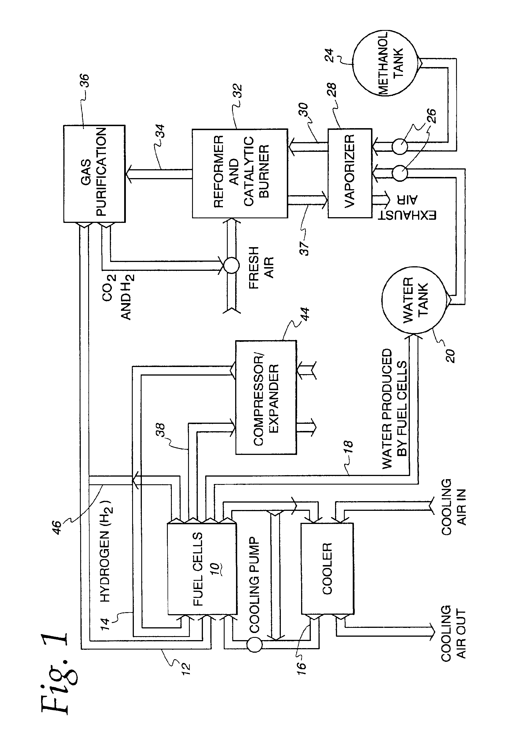
[0045]Turning now to FIG. 1, one type of fuel cell system embodying a reformer with which the invention may be used is ...


PUM

PropertyMeasurementUnit
thicknessaaaaaaaaaa
thicknessaaaaaaaaaa
angleaaaaaaaaaa

Abstract

A vaporizer, a fuel cell system including the vaporizer, and a method of vaporizing fuel in a fuel cell system are disclosed. The fuel cell system includes a fuel reservoir (24) for storing a liquid fuel and a fuel cell (10) for consuming a fuel and generating electricity therefrom. A fuel vaporizer (28) is interposed between the fuel reservoir (24) and the fuel cell (10) for receiving liquid fuel and vaporizing it and delivering it ultimately to the fuel cell (10). The fuel vaporizer (28) includes a heat exchanger which includes a hot fluid inlet (65), a hot fluid outlet (67) and a core (50) interconnecting the inlet (65) and the outlet (68). The core (50) has alternating fuel flow structures (68) and hot fluid structures (69) with the fuel flow structures (68,69) having an inlet (56) and an outlet (58).

Description

FIELD OF THE INVENTION[0001]This invention relates to fuel cell systems of the type including a reformer that creates a hydrogen rich gas for use in the fuel cell from a liquid fuel whose composition includes hydrogen. More specifically, the invention relates to the vaporization of the fuel prior to its admission to the reformer.BACKGROUND OF THE INVENTION[0002]Recent years have seen a marked increase in interest in fuel cells for the generation of electric power. One area where interest is high is in the design of propulsion systems for vehicles. As is well known, a typical fuel cell combines hydrogen and oxygen to generate electricity which may then be used to power an electric motor which can be used to provide propulsion for a vehicle.[0003]More recently, there have been a variety of proposals of fuel cell systems employing a so-called reformer. Reformers are chemical processors which take an incoming stream of a hydrocarbon containing or hydrocarbon based material and react it ...

Claims


Application Information

Patent Timeline
Patent Type & Authority Patents(United States)
IPC IPC(8): F28F3/08F28F13/00F28F13/08F28D9/00B01B1/00C01B3/38H01M8/04H01M8/06
CPCF28D9/005F28F3/086F28F13/08H01M8/0618H01M8/0625F28D2021/0043H01M8/04208H01M8/0668Y02E60/50
Inventor REINKE, MICHAEL J.WATTELET, JONATHANVOSS, MARK G.WEISSER, MARCMOTZET, BRUNOTHUMM, SVENGRANETZKE, DENNIS C.
Owner MODINE MFG CO
Learn More