Video image coding apparatus with individual compression encoding sections for different image divisions

a video image and coding apparatus technology, applied in the field of video image coding apparatus, can solve the problems of difficult implementation of encoding apparatus, difficult operation of apparatus and circuit control, and inapplicability, and achieve the effect of reducing the difference in picture quality

Inactive Publication Date: 2005-10-11
RAKUTEN INC
View PDF11 Cites 7 Cited by
  • Summary
  • Abstract
  • Description
  • Claims
  • Application Information

AI Technical Summary

Benefits of technology

[0010]It is an object of the present invention to provide a video image coding apparatus which realizes appropriate allocation of an information amount to individual image divisions to reduce the difference in picture quality among different divisions of a decoded image.

Problems solved by technology

However, it is difficult to implement an apparatus for encoding such a video image of a high resolution as a video image of a high definition television (HDTV) broadcast using a single encoder with the circuit technique and the LSI technique at present.
Where the technique just described is adopted, if the encoders are controlled so as to operate equivalently to a single encoder by taking such a method that information is always interchanged between the encoders, then this makes the apparatus and circuit control much complicated and is not practical.
However, a property of a video image as represented by a spatial complexity or a magnitude of a movement of an input video image is usually different among different portions of the image.
Accordingly, if an allocation information amount which depends upon the bit rate is simply divided equally and is allocated to and encoded by a plurality of encoders which operate independently of each other, then this gives rise to a problem that appropriate information amounts are not allocated to the encoders and a difference in picture quality appears among different divisions of a decoded image.
In the worst case, a partial rupture in picture quality or a trouble of a buffer arises.
Accordingly, the system described has a problem that appropriate allocation of the information amount of an entire image or efficient utilization of information by providing a comparatively greater amount of information to a portion which requires a comparatively great amount of information but reducing the amount of information at a portion which does not require a great amount of information is not realized.

Method used


Image

  • Video image coding apparatus with individual compression encoding sections for different image divisions
  • Video image coding apparatus with individual compression encoding sections for different image divisions
  • Video image coding apparatus with individual compression encoding sections for different image divisions

Examples


first embodiment

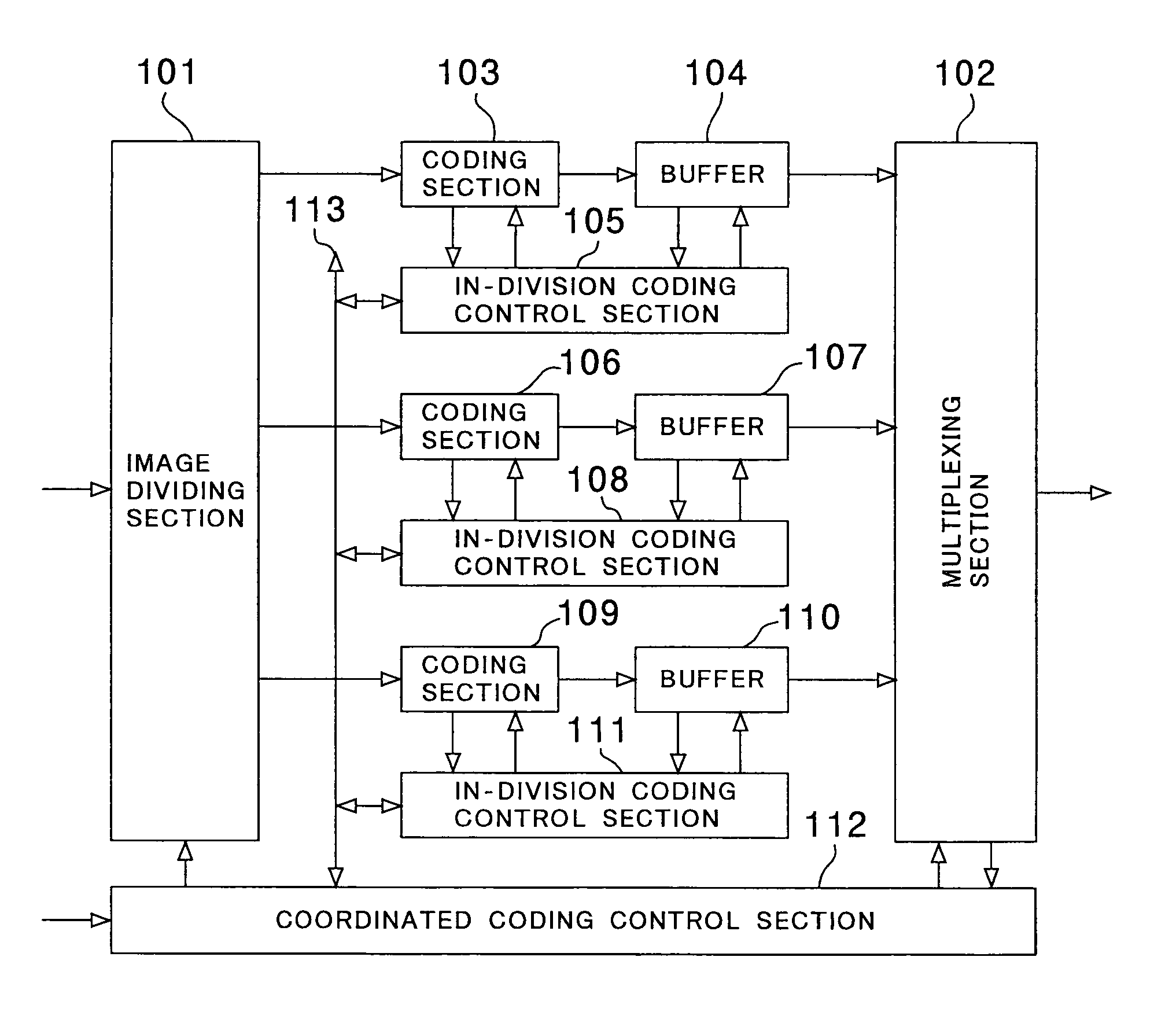
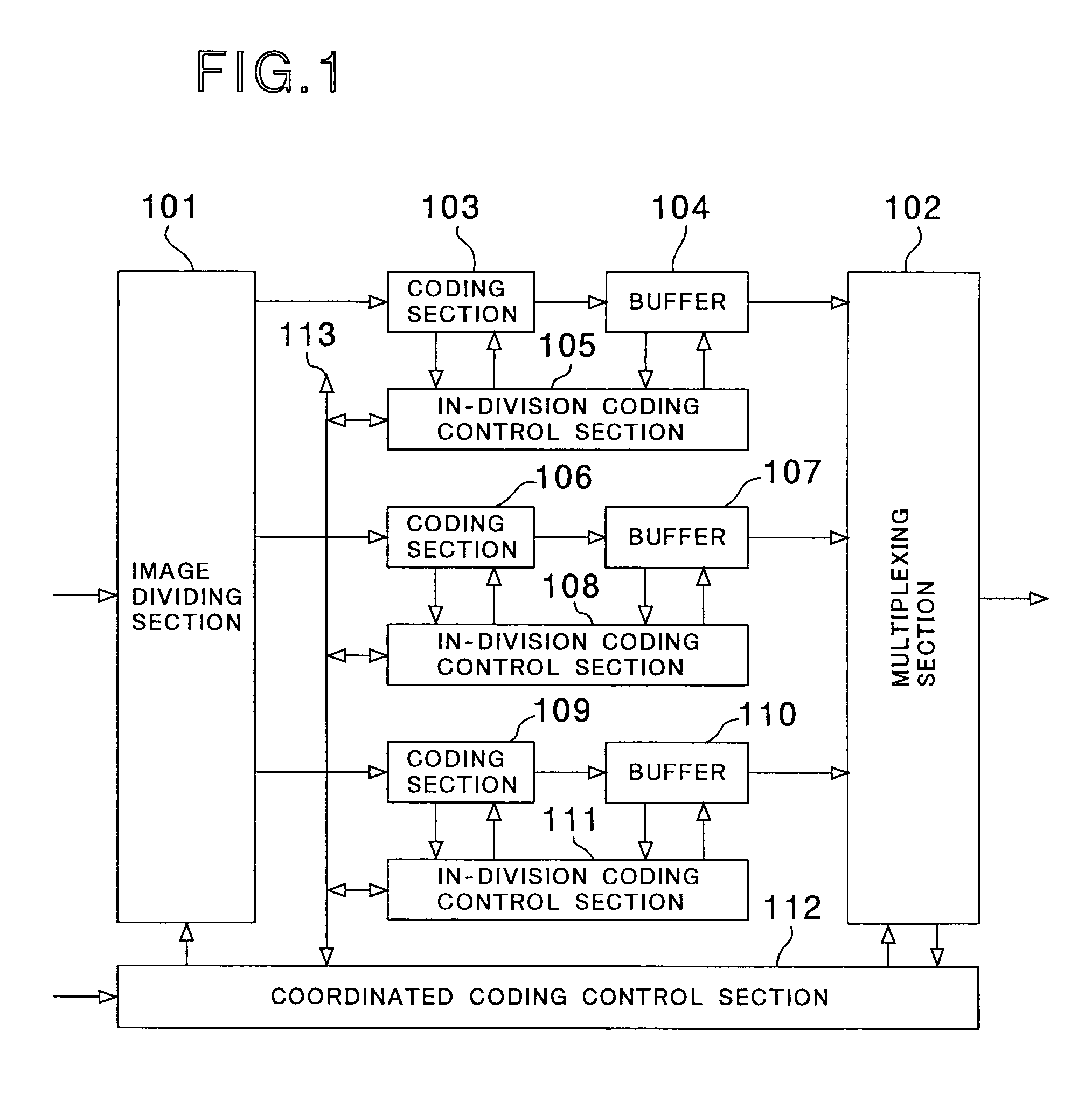
[0024]Referring first to FIG. 1, there is shown a video image coding apparatus to which the present invention is applied. The present video image coding apparatus includes an image dividing section 101 for dividing an input image and outputting resulting image divisions, a plurality of coding sections 103, 106 and 109 for individually coding the image divisions outputted from the image dividing section 101, a plurality of buffers 104, 107 and 110 for storing output streams of the coding sections 103, 106 and 109, respectively, a plurality of in-division coding control sections 105, 108 and 111 for controlling coding of the coding sections 103, 106 and 109, respectively, and a multiplexing section 102 for multiplexing the image division bit streams outputted from the buffers 104, 107 and 110 into a final stream and outputting the final stream. Further, a coordinated coding control section 112 is connected to the in-division coding control sections 105, 108 and 111 over a communicatio...

second embodiment

[0032]FIG. 4 shows another video image coding apparatus to which the present invention is applied. The video image coding apparatus of the present embodiment includes an image dividing section 401, a plurality of coding sections 403, 406 and 409, a plurality of buffers 404, 407 and 410, a plurality of in-division coding control sections 405, 408 and 411, a multiplexing section 402 and a communication bus 413 which are similar to the image dividing section 101, coding sections 103, 106 and 109, buffers 104, 107 and 110, in-division coding control sections 105, 108 and 111, multiplexing section 102 and communication bus 113 of the video image coding apparatus of the first embodiment described hereinabove with reference to FIG. 1, respectively. The video image coding apparatus of the present embodiment further includes a general control section 412 in place of the coordinated coding control section 112.

[0033]The video image coding apparatus of the second embodiment shown in FIG. 4 is s...

third embodiment

[0036]FIG. 5 shows a further video image coding apparatus to which the present invention is applied. The video image coding apparatus of the present embodiment includes an image dividing section 501, a plurality of coding sections 503, 506 and 509, a plurality of buffers 504, 507 and 510, a plurality of in-division coding control sections 505, 508 and 511, a multiplexing section 502, a coordinated coding control section 512 and a communication bus 513 which are similar to the image dividing section 101, coding sections 103, 106 and 109, buffers 104, 107 and 110, in-division coding control sections 105, 108 and 111, multiplexing section 102, coordinated coding control section 112 and communication bus 113 of the video image coding apparatus of the first embodiment described hereinabove with reference to FIG. 1, respectively. The video image coding apparatus of the present embodiment additionally includes a memory 514 for storing various parameters.

[0037]More particularly, the memory ...


PUM


Abstract

A video image coding apparatus which realizes appropriate allocation of an information amount to individual image divisions to reduce the difference in picture quality among different divisions of a decoded image. An input video image signal is into a plurality of image divisions by an image dividing section, and the image divisions are compressed coded by a plurality of coding sections. Resulting compression encoded data are multiplexed by a multiplexing section re-construct compression encoded data, and the compression encoded data are outputted as a compression stream. A coordinated coding control section receives some or all of coding parameters, image status parameters and coding result parameters of the coding sections and adjusts the parameters to be used for compression encoding by the coding sections in a control period or under a control condition determined in advance.

Description

BACKGROUND OF THE INVENTION[0001]1. Field of the Invention[0002]The present invention relates to a video image coding apparatus for compression encoding a video image, and more particularly to a video image coding apparatus wherein an input image is divided into image divisions and the image divisions are parallelly coded.[0003]2. Description of the Related Art[0004]A video image coding apparatus has made rapid progress particularly in recent years. For example, development of image communication and digital broadcasting which adopt the ISO / IEC13818-2 (MPEG-2 VIDEO) is proceeding at present. For coding of such a standard television signal as is prescribed in the ITU-R.601, a particularly high processing speed is not required, and therefore, an apparatus for the coding can be implemented using a single encoder even with a circuit technique and an LSI technique at present.[0005]However, it is difficult to implement an apparatus for encoding such a video image of a high resolution as a...

Claims


Application Information

Patent Timeline
Patent Type & Authority Patents(United States)
IPC IPC(8): H04N7/24H04N7/12H03M7/30H04N19/103H04N19/00H04N19/115H04N19/119H04N19/134H04N19/136H04N19/137H04N19/14H04N19/146H04N19/176H04N19/423H04N19/436H04N19/85
CPCH04N19/15H04N19/61H04N19/124H04N19/152H04N19/154H04N19/162H04N19/17
Inventor NOGAKI, SATOSHI
Owner RAKUTEN INC
Why Eureka
Try Eureka