Load variation tolerant radio frequency (RF) amplifier

Active Publication Date: 2005-10-11
SKYWORKS SOLUTIONS INC
View PDF6 Cites 133 Cited by
  • Summary
  • Abstract
  • Description
  • Claims
  • Application Information

AI Technical Summary

Problems solved by technology

Minimizing the size and cost of a portable communication transceiver are typically the greatest challenges facing the designers of such devices.
Without a protective isolator or other special protective circuitry, this variation in the impedance presented to the power amplifier causes the performance of t

Method used


Image

  • Load variation tolerant radio frequency (RF) amplifier
  • Load variation tolerant radio frequency (RF) amplifier
  • Load variation tolerant radio frequency (RF) amplifier

Examples


Embodiment Construction

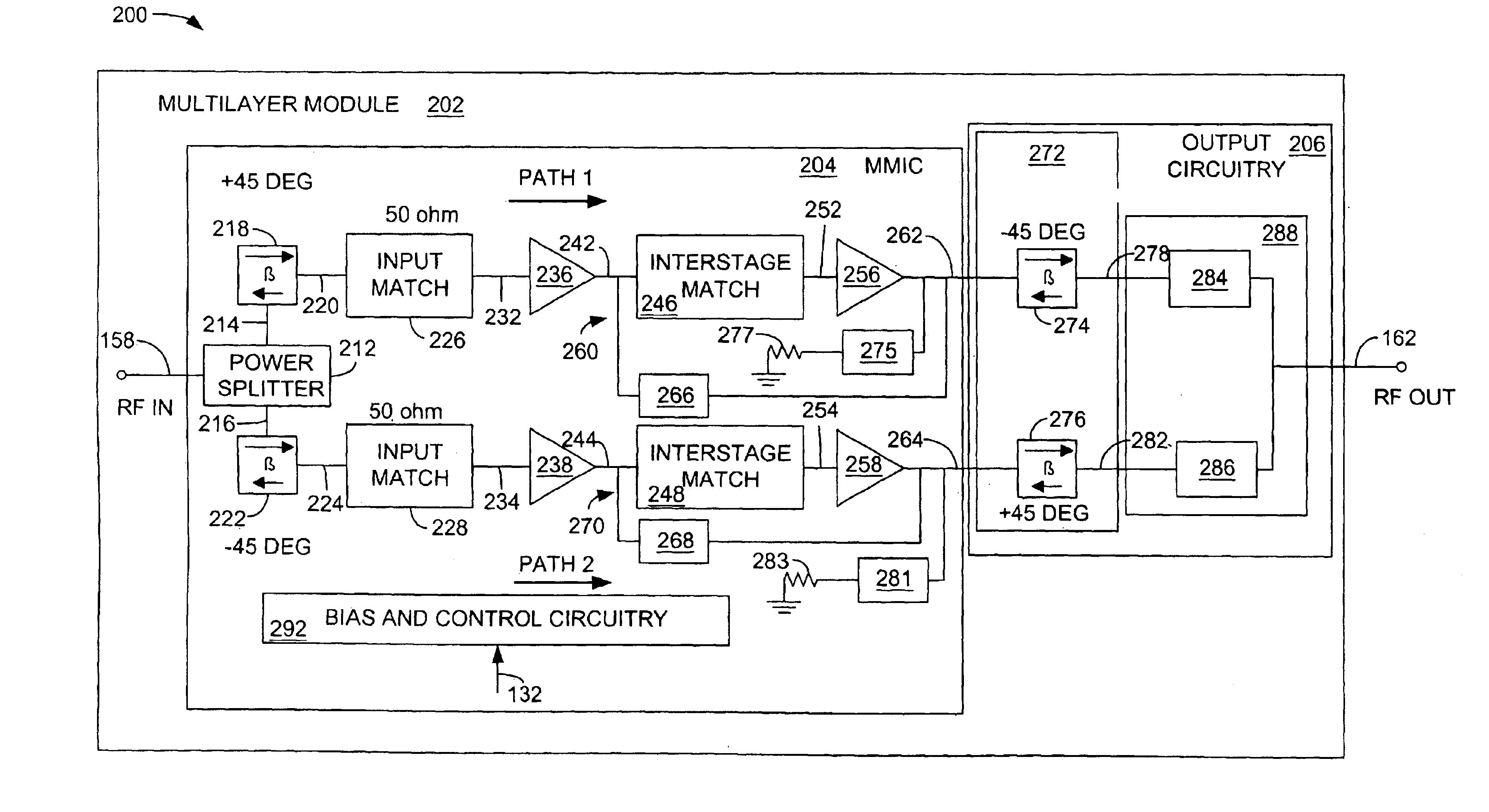
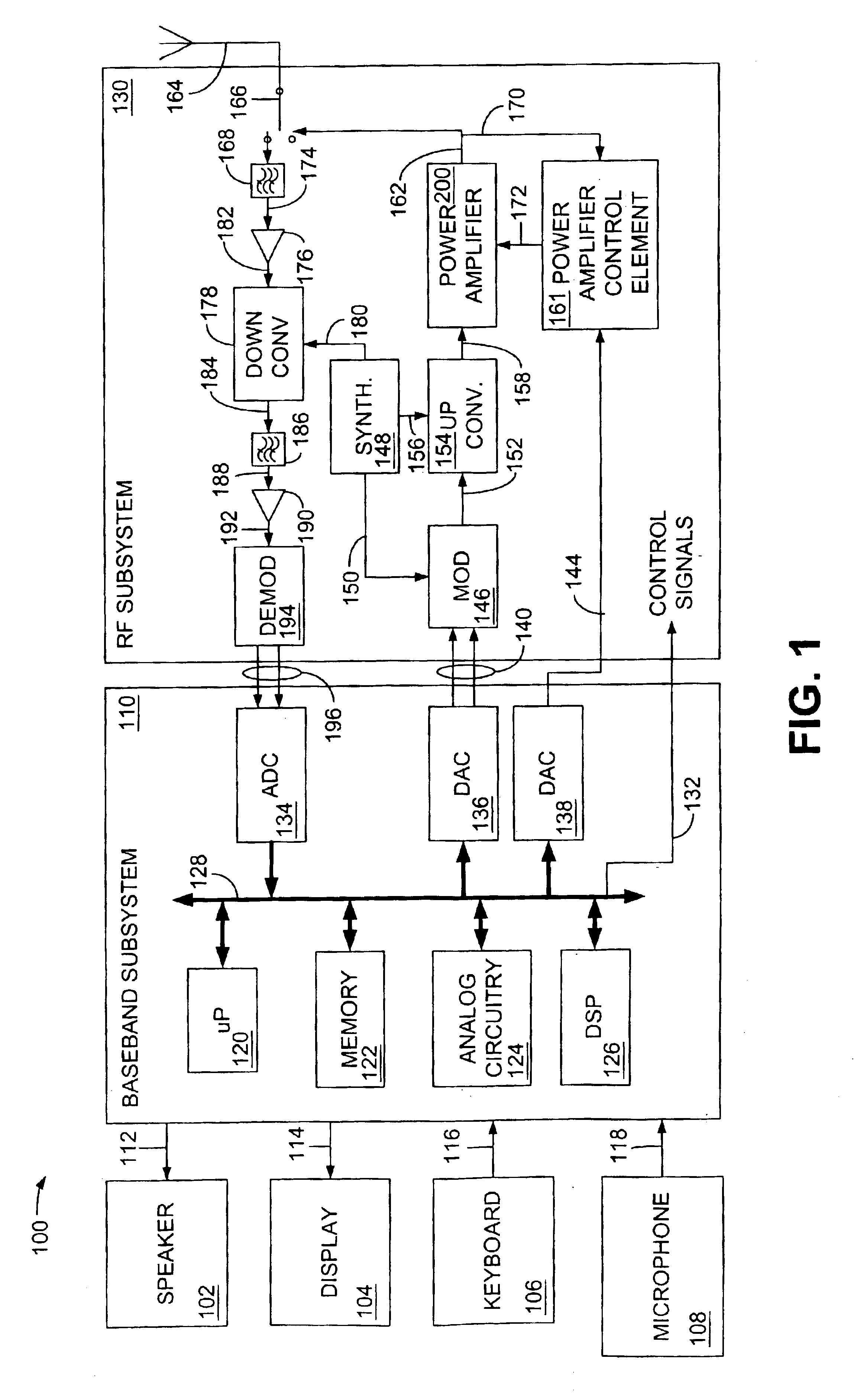
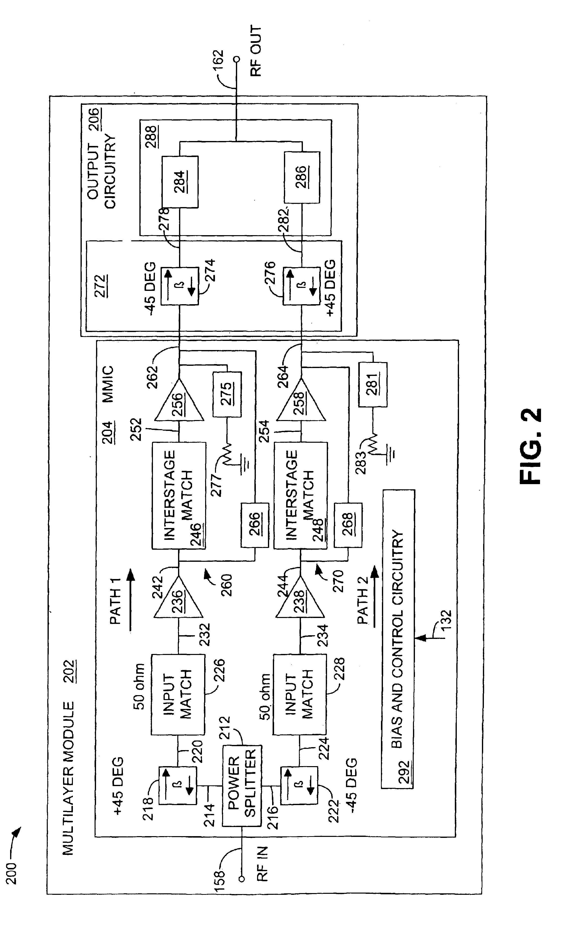
[0014]Although described with particular reference to a portable transceiver, the phase shift and impedance transformation element and / or the power combiner and impedance transformation element can be implemented in any balanced power amplification system where it is desirable to minimize cost and / or size by eliminating one or more isolators at the output of the power amplifier. In a preferred embodiment, the power amplifier including the phase shift and impedance transformation element and the power combiner and impedance transformation element are implemented in hardware, as will be described below. The hardware portion of the invention can be implemented using specialized hardware elements and logic. Furthermore, the hardware implementation of the phase shift and impedance transformation element, as well as the power combiner and impedance transformation element can include any or a combination of the following technologies, which are all well known in the art: discrete circuit c...


PUM


Abstract

A power amplifier having a phase shift and impedance transformation element is disclosed. The power amplifier comprises a plurality of amplification paths, a first phase shift element at an input of each amplification path and a second phase shift element at an output of each amplification path. The amplifier also comprises an impedance transformation element associated with the second phase shift element and a power combiner configured to combine an output of each amplification path into a single output.

Description

BACKGROUND OF THE INVENTION[0001]1. Field of the Invention[0002]This invention relates generally to the generation and control of radio frequency (RF) transmission power, minimizing cost, and reducing the size of a portable communications device. More particularly, the invention relates to an RF amplifier that is tolerant to load variation.[0003]2. Related Art[0004]With the increasing availability of efficient, low cost electronic modules, mobile communication systems are becoming more and more widespread. For example, there are many variations of communication schemes in which various frequencies, transmission schemes, modulation techniques and communication protocols are used to provide two-way voice and / or data communications in a handheld, telephone-like communication transceiver, a wireless personal digital assistant (PDA) or computer interface. While the different modulation and transmission schemes each have advantages and disadvantages, common goals for all of these devices ...

Claims


Application Information

Patent Timeline
IPC IPC(8): H04B1/04H04B5/00H04B5/06
CPCH03F3/602H04B1/0458H04B5/0012H04B5/06H03F1/08H03F3/20H04B1/38
Inventor CHANG, SHIAW W.FINLAY, HUGH J.CHENG, NAI-SHUOPARK, BON-SEOK
Owner SKYWORKS SOLUTIONS INC
Why Eureka
Try Eureka