Auto-switching system for switch-over of gas storage and dispensing vessels in a multi-vessel array

a multi-vessel array and auto-switch technology, applied in the direction of packaging goods, container discharging methods, separation processes, etc., can solve the problems of gas flow shut-down, pressure to exceed system set point limits, pressure spike,

Inactive Publication Date: 2005-10-18
ENTEGRIS INC
View PDF8 Cites 48 Cited by
  • Summary
  • Abstract
  • Description
  • Claims
  • Application Information

AI Technical Summary

Benefits of technology

[0019]In another aspect, the invention relates to a method of substantially reducing pressure variation of pumped gas discharged from a pump in a gas supply and dispensing system comprising an array of at least two gas storage and dispensing vessels arranged for sequential on-stream dispensing operation involving switchover from a first vessel to a second vessel in the array, wherein the pump is coupled in gas flow communication with the array for pumping of gas derived from an on-stream one of the vessels in the array, and discharge of pumped gas,

Problems solved by technology

The proportional integral derivative (PID) control logic that is employed with the pump in a usual arrangement cannot react quickly enough to slow the pump to avoid the impact of the pressure change, so that a pressure spike occurs as a result at the outlet of the fast running pump.
In a sub-atmospheric pressure system, e.g., as employed for ion implantation in which sub-atmospheric operation of the implant chamber represents an optimal process arrangement, this pressure spike can cause pressure to exceed system set point limits.
Such overpressure condition in turn can cause alarms to be actuated, and in an extreme pressure variation condition, the safety monitoring elements of the gas delivery system may cause shut-down of the gas flow and undesired stoppage of the downstream gas-consuming process.

Method used


Image

  • Auto-switching system for switch-over of gas storage and dispensing vessels in a multi-vessel array
  • Auto-switching system for switch-over of gas storage and dispensing vessels in a multi-vessel array
  • Auto-switching system for switch-over of gas storage and dispensing vessels in a multi-vessel array

Examples


Embodiment Construction

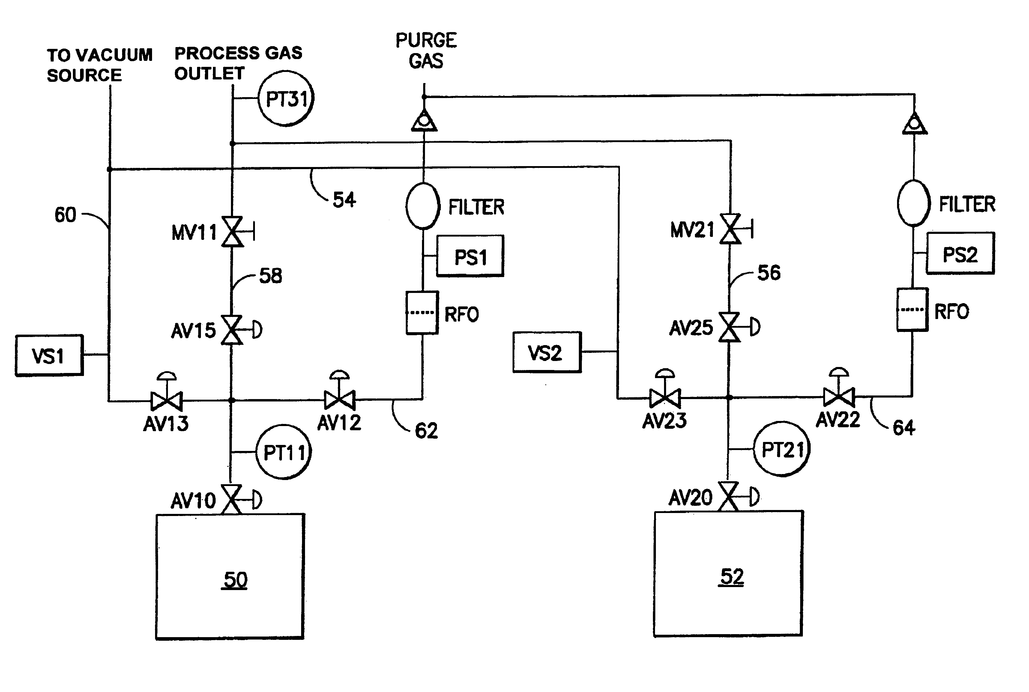
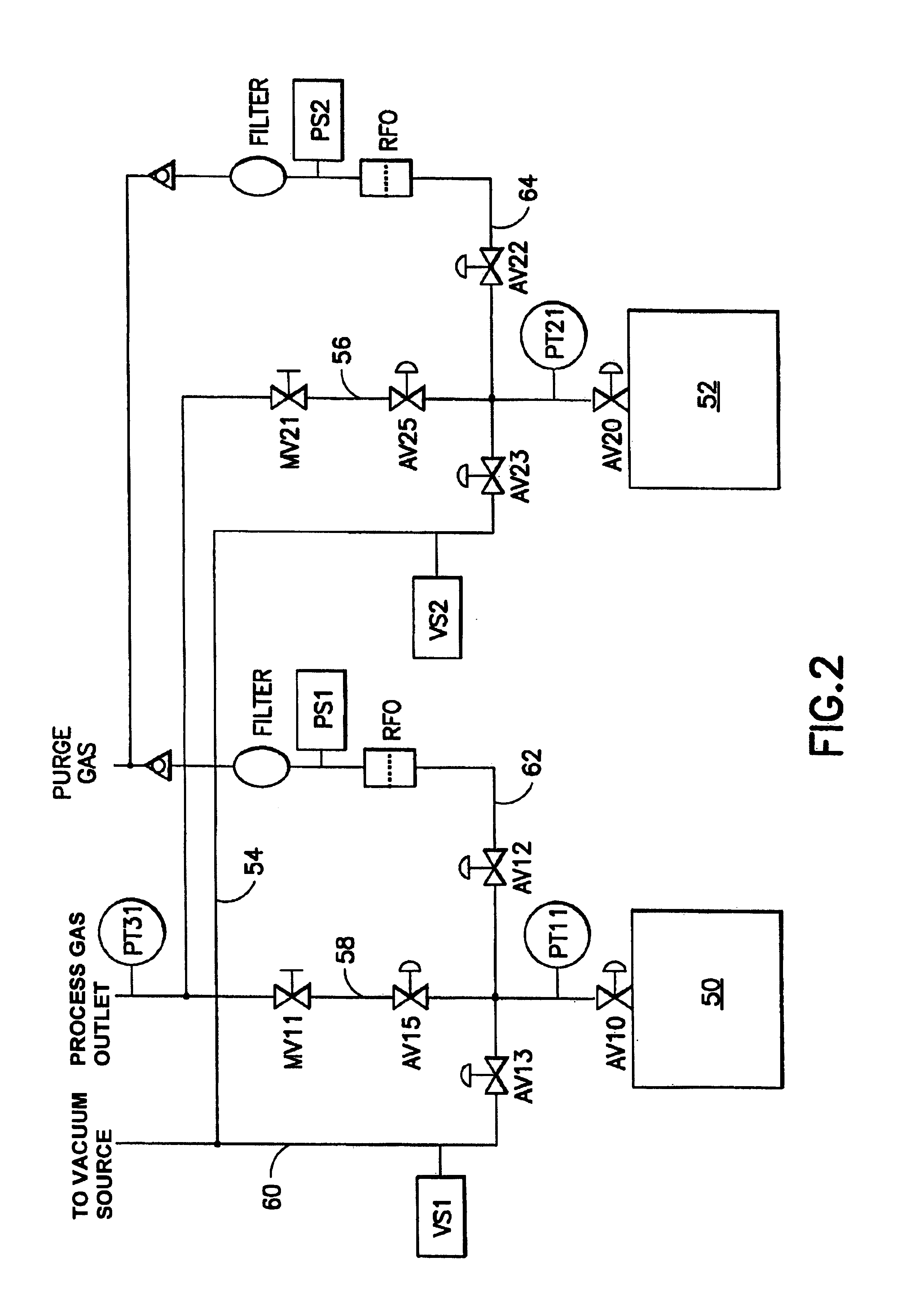
[0049]The present invention provides an automated switching apparatus and method for gas delivery systems in which pumping / extractor apparatus is coupled with multiple vessel arrays including vessels of the type described in the aforementioned U.S. Pat. Nos. 5,518,528; 6,101,816; 6,089,027; and 6,343,476.

[0050]The present invention is based on the discovery that the adverse pressure effects of switch-over of fluid storage and dispensing vessels in a multi-vessel array can be eliminated by the provision of a time delay in the automated change-over system, to allow the pumping components to be signaled in advance of the automated change-over, so that the pumping components responsively operate to prevent the transmission of a pressure spike to the inlet of a fast-running pump that is employed to effect flow of gas through the flow circuitry to the downstream gas-consuming process.

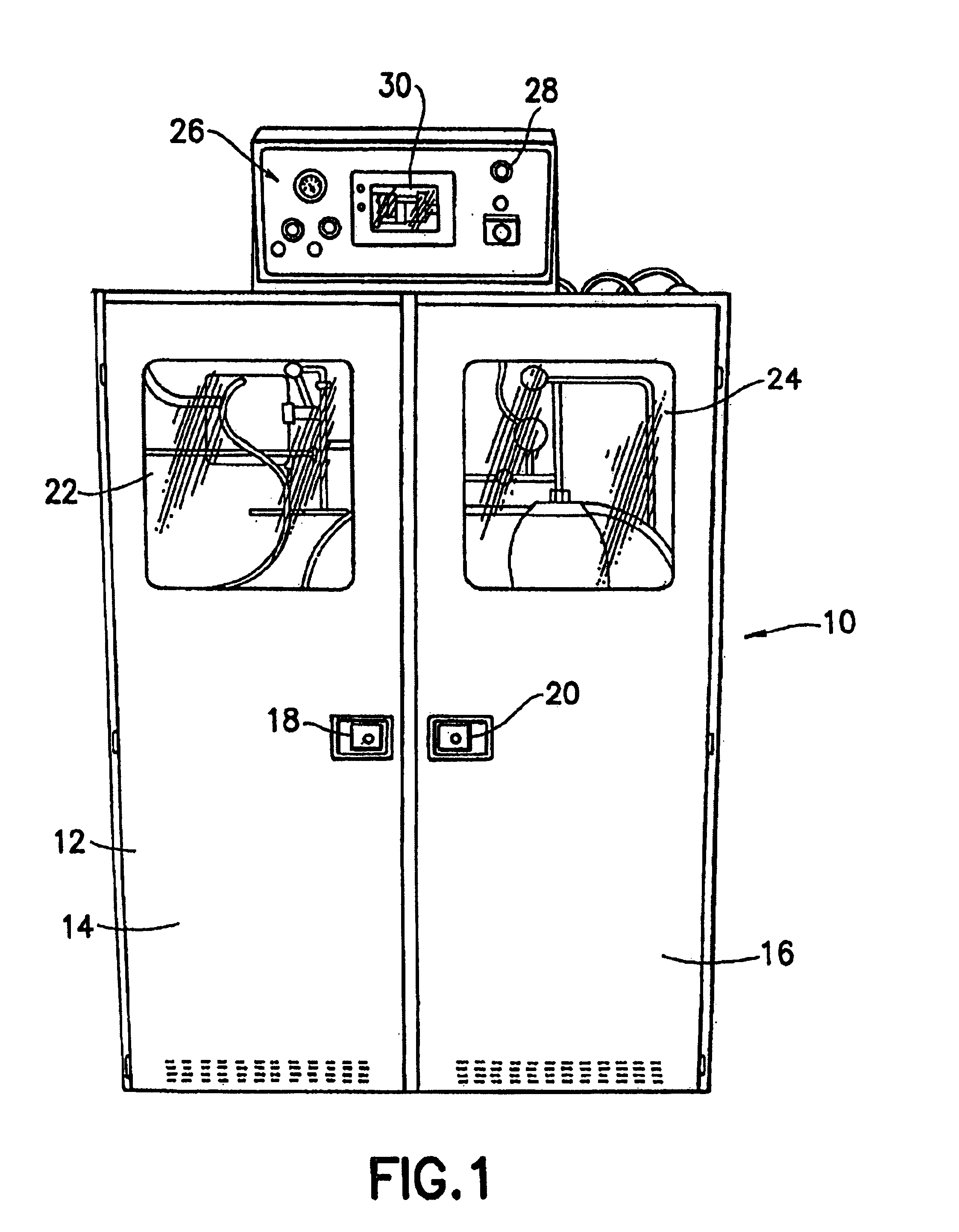
[0051]FIG. 1 is a front view of a reduced pressure module gas delivery system 10 with vessel switchover ca...


PUM

PropertyMeasurementUnit
volumeaaaaaaaaaa
pressureaaaaaaaaaa
weightaaaaaaaaaa

Abstract

A gas storage and dispensing system, including multi-vessel arrays of gas dispensing vessels that require successive change-over to provide ongoing supply of gas to a gas-consuming process, with a pump coupled in gas flow communication with the array. The system is provided with capability for time delay auto-switchover sequencing of the switchover operation in which an endpoint limit sensing of an on-stream gas dispensing vessel is responsively followed by termination of gas flow to the pump, inactivation of the pump, autoswitching of vessels, reinitiation of gas flow to the pump and reactivation of the pump. The system minimizes the occurrence of pressure spikes at the pump outlet in response to pressure variation at the pump inlet incident to switchover of gas supply from one vessel to another in the multi-vessel array.

Description

FIELD OF THE INVENTION[0001]The present invention relates generally to gas storage and dispensing vessels, and particularly to multi-vessel arrays that require successive change-over to provide ongoing supply of gas to a gas-consuming process unit. In a specific aspect, the invention relates to a gas cabinet containing multiple gas storage and dispensing vessels providing gas to semiconductor manufacturing tools in a semiconductor manufacturing facility, and to auto-switching systems for switch-over of vessels to maintain continuity of gas dispensing operation.DESCRIPTION OF THE RELATED ART[0002]The physical adsorbent-based gas storage and dispensing system disclosed in Tom et al. U.S. Pat. No. 5,518,528 has revolutionized the transportation, supply and use of hazardous gases in the semiconductor industry. The system includes a vessel holding a physical adsorbent medium such as molecular sieve or activated carbon, having sorptive affinity for the gas that is to be stored in and sele...

Claims


Application Information

Patent Timeline
Patent Type & Authority Patents(United States)
IPC IPC(8): B65B1/04B01DF17C7/00F17C13/02F17C13/04
CPCF17C7/00F17C13/025F17C13/045F17C2205/0111F17C2205/013F17C2205/0341F17C2223/0123F17C2223/035F17C2227/042F17C2227/044F17C2227/045F17C2250/032F17C2250/043F17C2270/0518B65B1/04F17C13/00
Inventor WODJENSKI, MICHAEL J.
Owner ENTEGRIS INC
Why Eureka
Try Eureka