Office chair

a technology for office chairs and seats, applied in the field of chairs, can solve the problems of the wide variety of tasks that manufacturers must consider, and the difficulty of manufacturers confronting the various preferences of individual users, and achieve the effects of reducing manufacturing costs, improving aeration, and simplifying the manufacturing of seats

Inactive Publication Date: 2005-10-18
HERMAN MILLER INC
View PDF33 Cites 142 Cited by
  • Summary
  • Abstract
  • Description
  • Claims
  • Application Information

AI Technical Summary

Benefits of technology

[0018]Accordingly, a fabric seat is provided that simplifies the manufacture of the seat. The fabric seat includes a seat frame with a series of grasping members along the circumference of the seat frame. Preferably, the grasping members are teeth that protrude up through holes in the fabric, thereby securing the fabric to the seat frame. In addition, a knit fabric material with interlocked threads is preferred. A cover is also provided that can be installed onto the seat frame by flexing the cover and snapping it onto the seat frame. The cover traps the fabric between the seat frame and the cover and protects the user from being snagged by the grasping members.
[0019]A machine also provides a reliable procedure for installing the fabric onto the seat frame. The machine includes front, back, and side clamps for pre-stretching and final stretching the fabric. A pressing member presses the fabric against the seat frame and the grasping members. Preferably, the pressing member is a blade that presses the fabric down along the inner circumference of the grasping members. Guide members are also included that pull the fabric against the seat frame. Preferably, the guide members are attached to the clamps and are shaped like the outer circumference of the seat frame so that the fabric is pulled down tightly along the outer circumference of the grasping members.

Problems solved by technology

Manufacturers of office chairs have always faced a difficult task when trying to produce an office chair that will be suitable for a broad variety of different people.
Another difficulty that manufacturers must consider is the wide variety of tasks that different users perform in their office chairs.
Notwithstanding these difficulties, the most difficult issue that manufacturers must confront is the various preferences of individual users.
Some users find this reclining system undesirable, however, because of the rigid attachment of the seat and the back.
One especially undesirable result of this reclining system is that the front edge of the seat moves upward as the back is reclined.
These systems, however, produce friction and pulling between the back of the chair and the user's upper body because the back generally travels along a different angular rotation than the user's upper body.
One challenge in designing these types of reclining systems is achieving an optimal balance between the seat movement and back travel during reclining.
One problem with some reclining systems is that the leverage applied to the main spring changes as the back is reclined rearward.
This results in the user feeling less support from the back the further the user reclines rearward.
However, in these systems the vertical positioning of the actuating system in relation to the horizontal valve stem is usually quite critical.
This typically makes the manufacturing and assembly of the height adjustment system more expensive and complicated.
The manner of using these systems can also become complicated, thus confusing the user as he attempts to adjust the height of the chair.
In addition to these problems, some spring adjustment systems require a minimum amount of spring pressure at all times in order to function properly.
This combined procedure of compressing the spring while simultaneously installing the spring into the reclining system can become quite difficult and time consuming.
This procedure is also undesirable for chairs that are shipped unassembled directly to end users who may not have the special tools necessary to install the spring with the necessary preload stress.
Other users, however, prefer not to have arm rests on their chairs because the arm rests can obstruct the sides of the chair and can interfere with free movement into or out of the chair.
However, this manufacturing technique can be expensive and requires special manufacturing equipment that is not always readily available.

Method used


Image

  • Office chair
  • Office chair
  • Office chair

Examples


Embodiment Construction

Reclining System

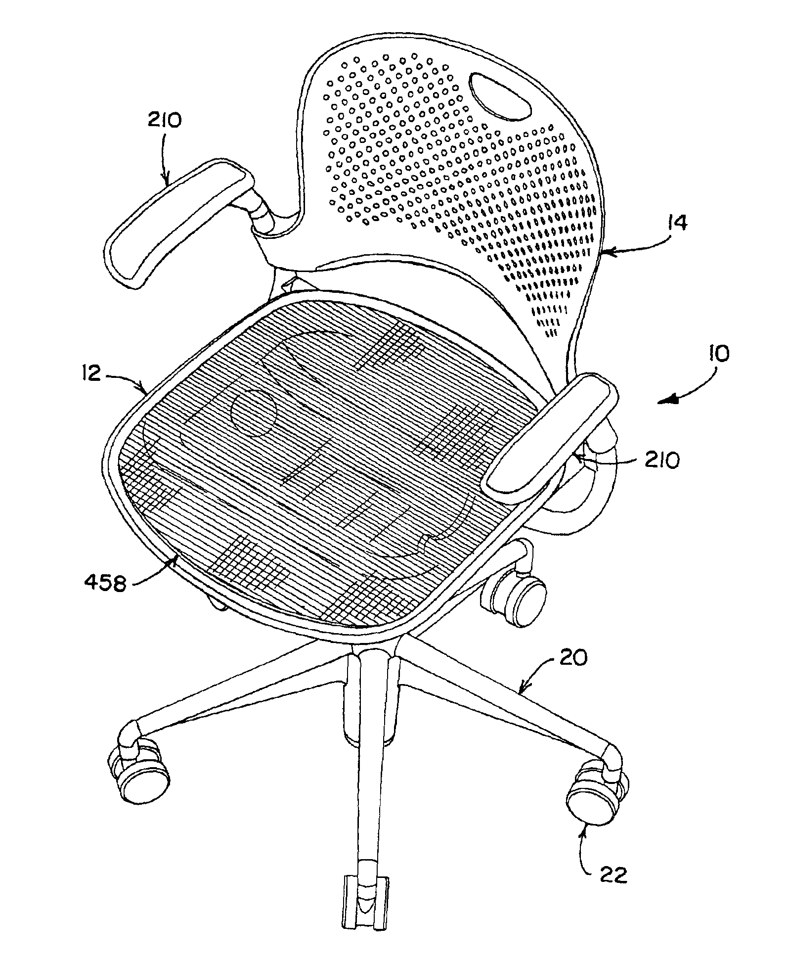
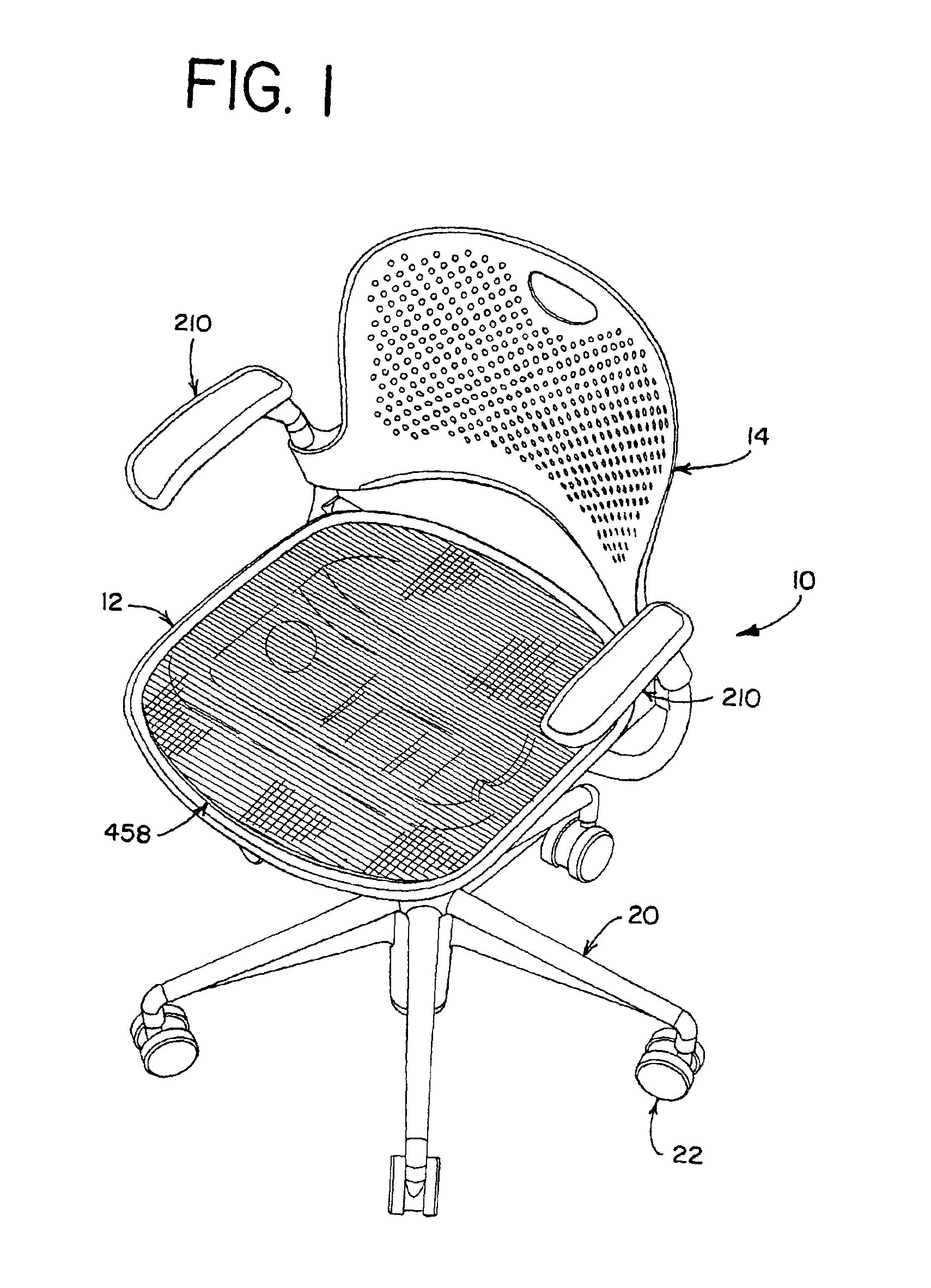
[0073]Turning now to the drawings, and particularly to FIG. 1, there is shown an office chair 10. A user sits in the office chair 10 by resting his upper legs and buttocks on the seat 12 of the chair 10. Although a variety of different seats can be used, a seat 12 like that disclosed below can be used. The user's legs extend down along the front of the chair 10 so that his feet are flat on the floor. In order to rest the user's upper body, the user can lean rearward and relax the back side of his upper body against the back 14 of the chair 10. Arm rests 210 are also provided so that the user can relax his arms on top of the arm rests 210. Although arm rests are not needed, and many styles of arm rests can be used, arm rests 210 like those disclosed below can be used. The seat 12 is supported along its underside by a chair stem assembly 18, and stability is provided by a number of legs 20 that rest on the floor. Casters 22 are provided on the bottom of the legs 20 to ...


PUM

PropertyMeasurementUnit
widthaaaaaaaaaa
angleaaaaaaaaaa
circumferenceaaaaaaaaaa

Abstract

A fabric seat for a chair and a method and machine for manufacturing the fabric seat. The fabric seat comprises a seat frame that supports the outer circumference of a fabric material. The seat frame comprises grasping members that secure the fabric to the seat frame and retain the desired stretch in the fabric. The grasping members can be teeth. A cover is also provided, which is snapped onto the circumference of the seat frame, to trap the fabric and protect the user from the grasping members.

Description

[0001]This application claims the benefit of U.S. Provisional Application No. 60 / 206,204, filed May 22, 2000, U.S. Provisional Application No. 60 / 206,205, filed May 22, 2000, and U.S. Provisional Application No. 60 / 206,457, filed May 22, 2000.FIELD OF THE INVENTION[0002]The present invention relates generally to chairs, and more particularly, to a seat.BACKGROUND[0003]An office chair is a well-known piece of furniture that allows a user to comfortably sit in the chair while performing various work tasks. Manufacturers of office chairs have always faced a difficult task when trying to produce an office chair that will be suitable for a broad variety of different people. One reason for this difficulty is that users of chairs vary greatly in their relative size and proportions. The heights of users, for example, can vary significantly, with some users being taller while others are shorter, and some users having longer trunk proportions while others have longer leg sections. In addition...

Claims


Application Information

Patent Timeline
Patent Type & Authority Patents(United States)
IPC IPC(8): A47C7/22A47C31/02A47C3/00A47C7/02A47C31/00A47C1/024A47C1/025A47C1/032A47C3/04A47C7/34A47C7/35A47C7/54A47C13/00
CPCA47C1/03272A47C3/00A47C3/04A47C7/282A47C31/02A47C1/03255A47C1/03266A47C7/546Y10T29/49867
Inventor VANDERIET, DOUGLAS M.RAETHER, DANIEL J.WEBER, JEFFKRUPICZEWICZ, TODD D.NYHUIS, ROBERT G.COFFIELD, TIMOTHY P.
Owner HERMAN MILLER INC
Why Eureka
Try Eureka