
Apparatus for the diameter checking of eccentric portions of a mechanical piece in the course of the machining in a grinding machine

a technology of eccentric parts and apparatus, which is applied in the direction of mechanical means, instruments, manufacturing tools, etc., can solve the problems of slow detection and processing operation, inability to determine whether any possible variations detected by either of the heads, and inability to guarantee satisfactory metrological performan

Inactive Publication Date: 2005-10-18
MARPOSS SPA
View PDF6 Cites 16 Cited by
  • Summary
  • Abstract
  • Description
  • Claims
  • Application Information

AI Technical Summary

Benefits of technology

[0006]An object of the present invention is to provide an apparatus for checking eccentric pins of small-size shafts, while the pins eccentrically rotate in the course of the machining in a grinding machine, that overcomes the drawbacks of the known apparatuses and provides good metrological performance and high standards of reliability and flexibility.

Problems solved by technology

Even though the utilization of a checking application of this type is simple, it cannot guarantee satisfactory metrological performances because, among other things, the diameter of the pin is “deduced” on the basis of checkings carried out by touching the same point of the surface in two opposite arrangements of the piece.
It is not possible to determine whether any possible variations detected by either of the two heads is due to diameter variations, to shape and / or eccentricity errors or to a combination of such factors.
Furthermore, the detecting and processing operation is slow and, whenever the nominal diameter dimensions of the piece to be checked vary, it is necessary to manually reset the application and consequently this implies machine down-time and considerable loss of time.

Method used


Image

  • Apparatus for the diameter checking of eccentric portions of a mechanical piece in the course of the machining in a grinding machine
  • Apparatus for the diameter checking of eccentric portions of a mechanical piece in the course of the machining in a grinding machine
  • Apparatus for the diameter checking of eccentric portions of a mechanical piece in the course of the machining in a grinding machine

Examples


Embodiment Construction

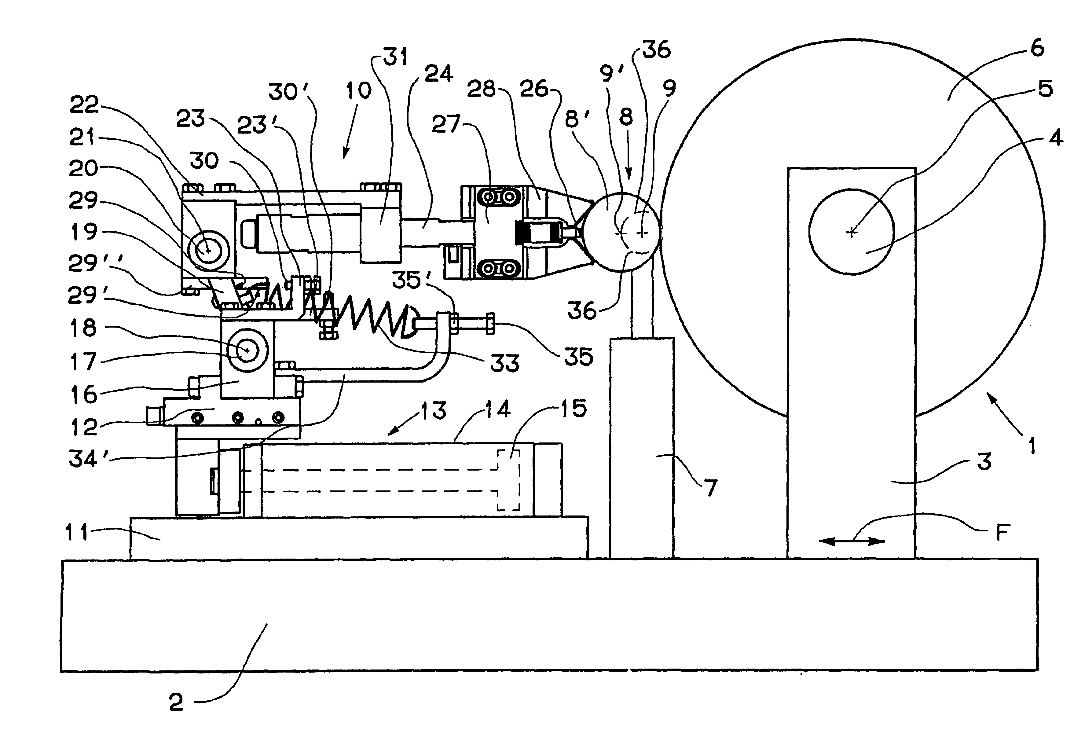
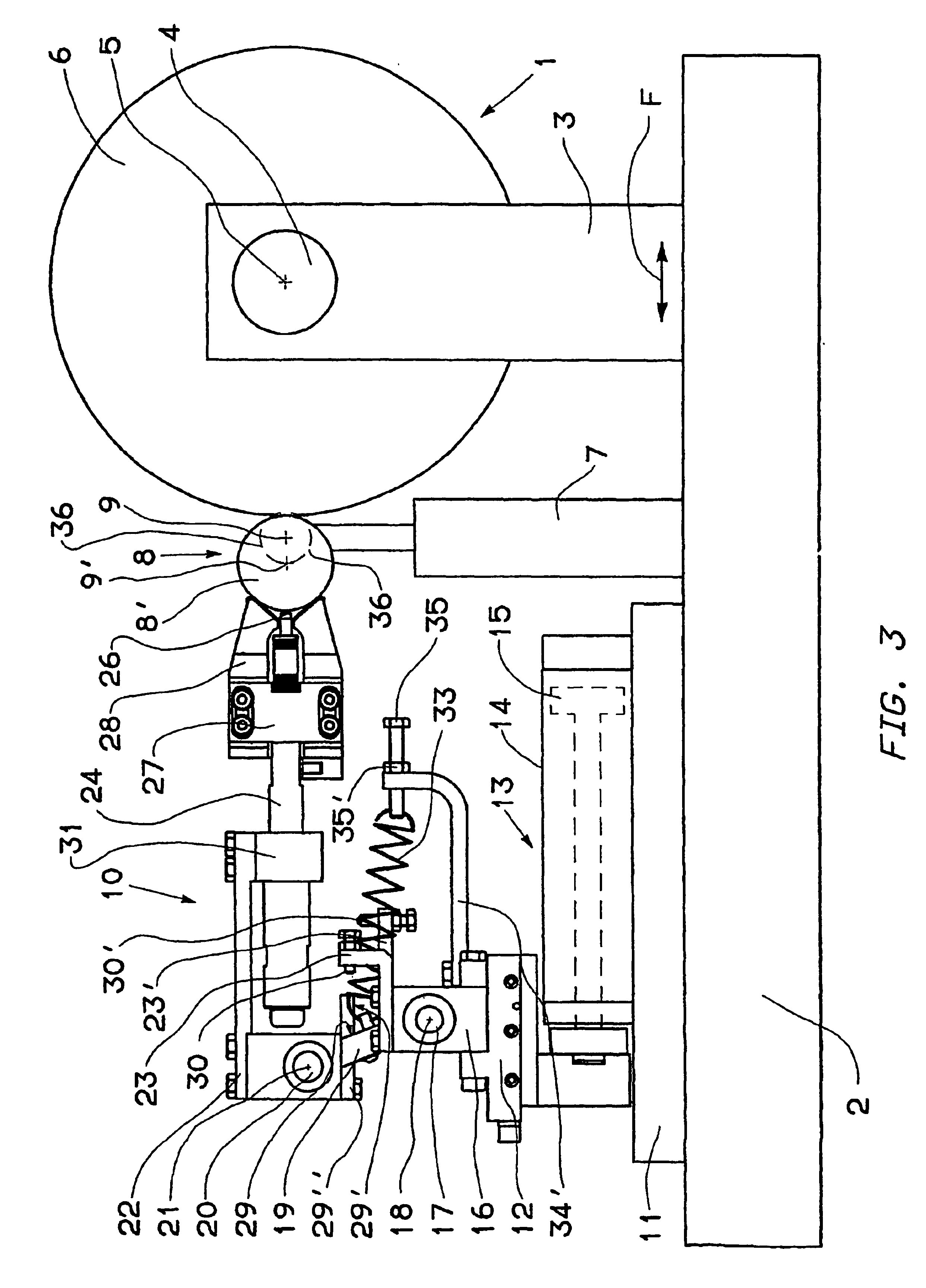
[0017]With reference to FIG. 3, a computer numerical control (“CNC”) grinding machine 1 includes a bed 2, to which there is coupled a grinding-wheel slide 3, for supporting a spindle 4, that defines the axis of rotation 5 of the grinding wheel 6. The grinding-wheel slide 3 can displace relative to bed 2 in a known way as indicated in FIG. 3 by arrow F.

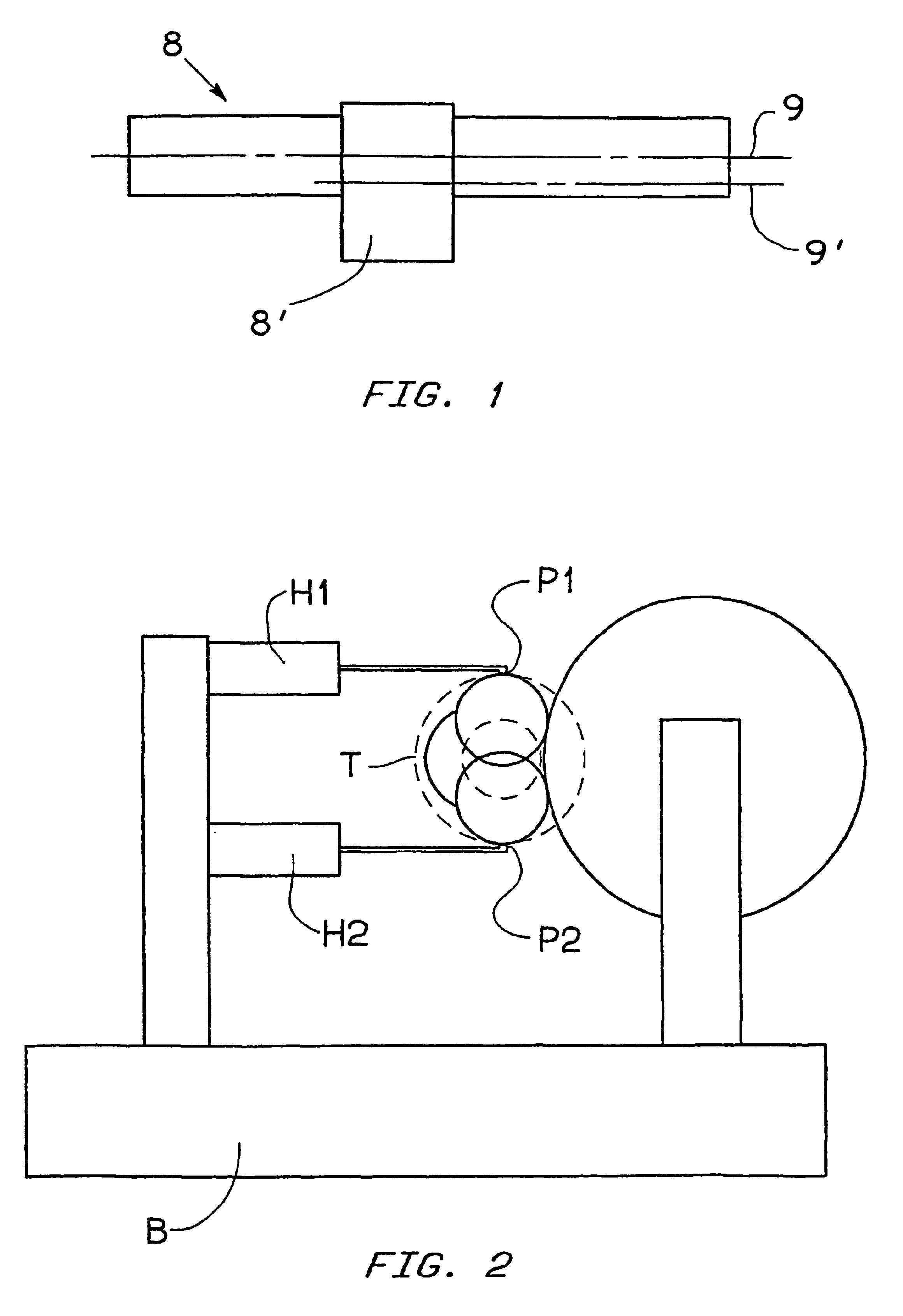
[0018]A worktable 7, carrying the piece to be checked—for example a shaft 8 for compressors with at least a cylindrical eccentric portion, or pin, 8′—is coupled to bed 2 between a spindle and a tailstock, not shown, that define the axis of rotation 9, coincident with the main geometrical axis of piece 8. Consequently, in the course of the rotation of piece 8, crankpin 8′ performs an eccentric motion about axis 9.

[0019]Moreover, there is coupled to bed 2 an apparatus 10—also shown in FIGS. 4 and 5—for checking, during the machining, the diametral dimensions and / or possible shape errors of pin 8′ of piece 8. The apparatus 10 is coupled t...


PUM


Abstract

An apparatus (10) for checking the diameter of an eccentric pin (8′) of a small-size shaft (8), for example a shaft for compressors, includes a support (16), a first arm (19) rotating with respect to the support (16), a second arm (22) rotating with respect to the first, a Vee-shaped reference device (28) carried by the second arm, a measuring device (25,26,24,37,38) associated with the reference device, limiting devices (29,29′,30,30′) for limiting the rotations of the arms and thrust means (33) for keeping the reference device in contact with the pin in the course of the checking. A hydraulic actuator (13) displaces the apparatus (10) from a rest condition to a checking condition, in which the reference device (28) is in contact with the pin (8′) to be checked, and vice versa.

Description

TECHNICAL FIELD[0001]The present invention relates to an apparatus for the diameter checking of a substantially cylindrical eccentric portion of a mechanical piece that defines a geometrical axis, during eccentric rotations of said portion about the geometrical axis, including a substantially Vee-shaped reference device, adapted for cooperating with the eccentric portion to be checked, a measuring device, movable with the reference device, and a support device for supporting the reference device and the measuring device, the support device including a support element, a first rotating, coupling element coupled to the support element so as to rotate about an axis of rotation parallel to the geometrical axis, a second rotating, coupling element that carries the reference device and the measuring device and is coupled to the first coupling element so as to rotate relative to it about an additional axis of rotation parallel to the geometrical axis and to the axis of rotation, and limiti...

Claims


Application Information

Patent Timeline
IPC IPC(8): B24B5/00B24B49/02B24B5/42B24B49/04G01B5/10
CPCB24B5/42B24B49/04
Inventor DALL'AGLIO, CARLO
Owner MARPOSS SPA
Learn More