Systems and methods for multi-channel analog to digital conversion

a multi-channel analog and digital technology, applied in the field of signal processing, can solve the problems of distorted and difficult to detect and measure, adc may not have enough dynamic range to handle strong interference and weak signals, and may not have desired signals, etc., to achieve the effect of increasing the effective dynamic range of an adc, increasing power efficiency and cost-effectiveness

Inactive Publication Date: 2005-10-18
L 3 INTEGRATED SYST +1
View PDF13 Cites 58 Cited by
  • Summary
  • Abstract
  • Description
  • Claims
  • Application Information

AI Technical Summary

Benefits of technology

[0010]Disclosed herein are systems and methods for analog to digital conversion that may be implemented by providing analog feedback to at least partially cancel one or more signals (e.g., one or more interfering signals present with one or more desired signals, one or more strong desired signals, etc.) at the analog input of an ADC, and that may be used in one embodiment to extend the effective dynamic range of an ADC. In this regard, the effective dynamic range of an ADC may be extended by detecting and isolating signals and using dig

Problems solved by technology

Under such conditions, the ADC may not have enough dynamic range to handle the strong interferer and weak signal simultaneously.
In this case, the ADC may become saturated by the strong interfering signal and the weak desired signal may be at best distorted and hard to detect and measure, and at worst may be rendered completely non-recoverable.
However, increasing the number of bits results in limited bandwidth or higher power consumption, large form factor, heat dissipation, and cost.
Furthermore, the current state of the art limits the amount of dynamic range that can be achieved by adding bits to an ADC.
However, the interference suppression capability of this approach is limited by the shape control of analog filters, and it is not possible with this approach to remove an interferer that is occupying the same spectral space as the weak signal.
While presenting an integrated approach with better form factor, this proposal suffers from similar drawbacks as upstream analog filtering.
Further, filter performance and flexibility provided by currently available noise-shaping ADCs is not as good

Method used


Image

  • Systems and methods for multi-channel analog to digital conversion
  • Systems and methods for multi-channel analog to digital conversion
  • Systems and methods for multi-channel analog to digital conversion

Examples


Embodiment Construction

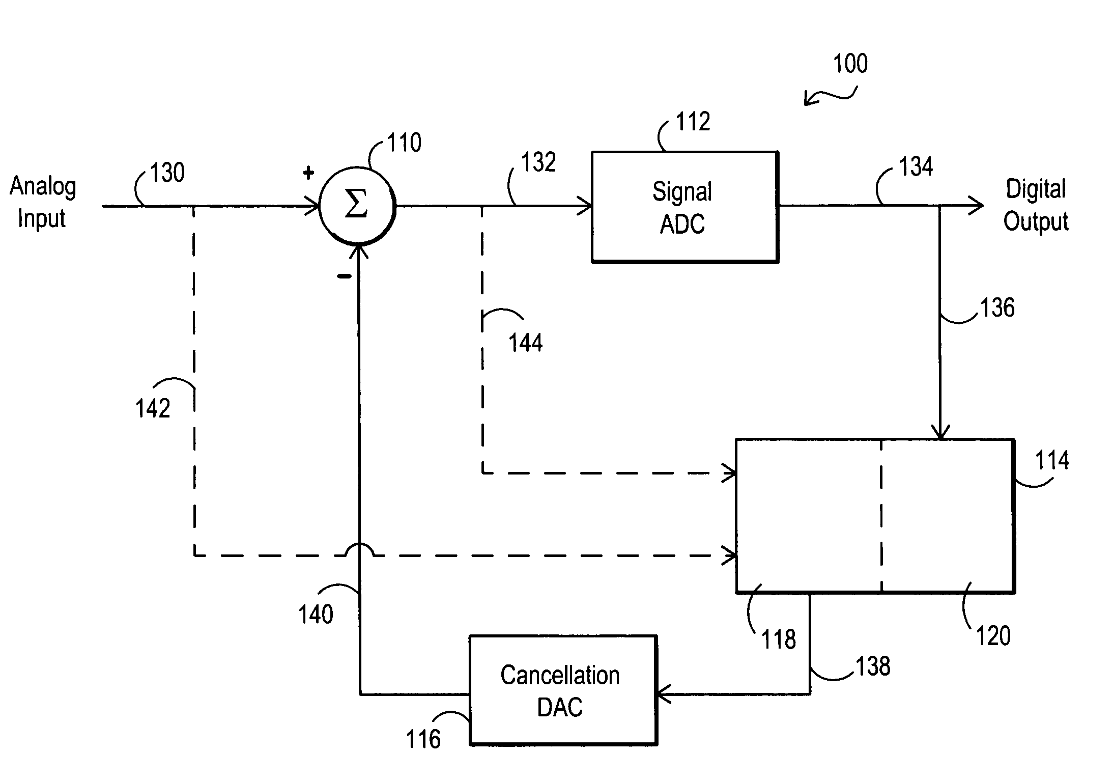
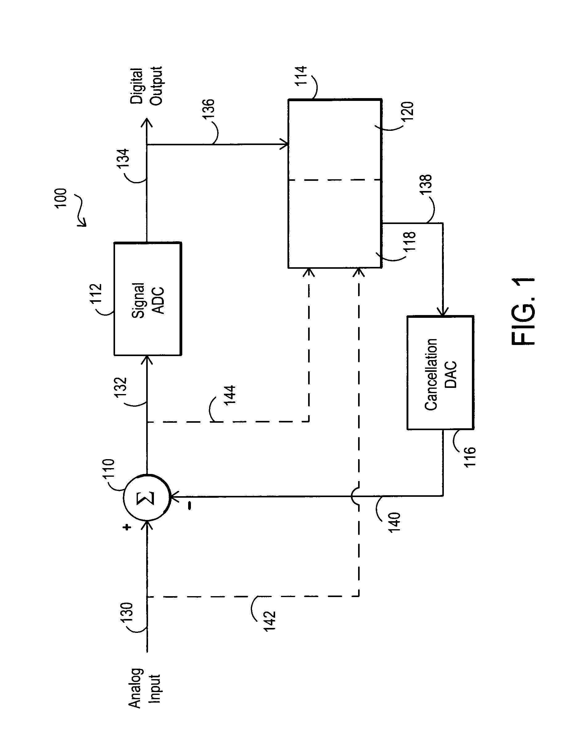
[0039]FIG. 1 illustrates an analog to digital conversion system 100 as it may be configured according to one embodiment of the disclosed systems and methods. As shown in FIG. 1, system 100 is configured to receive an analog input signal 130 and to provide a digital output signal 134. Analog input signal 130 may include one or more signals that without further modification would saturate signal ADC component 112. For example, analog input signal 130 may include one or more weak desired signals in the presence of one or more strong interferer signals that without further modification would saturate signal ADC component 112. Alternatively, analog input signal 130 may include one or more strong desired signals (with or without the presence of one or more interferer signals) that without further modification would saturate signal ADC component 112. ADC system 100 may be employed for the conversion of analog signals to digital signals (e.g., radio frequency signals, acoustic signals, etc....


PUM


Abstract

Systems and methods for analog to digital conversion that may be implemented using a digital to analog converter (DAC) to provide negative feedback to cancel signals at the input of an analog to digital converter (ADC), and that may be used to extend the effective dynamic range of an ADC. The systems and methods may be implemented in multi-channel environments.

Description

[0001]The present application is a continuation-in-part of co-pending U.S. patent application Ser. No. 10 / 866,532 filed Jun. 12, 2004 is still pending, the disclosure of which is incorporated herein by reference in its entirety. The present application also claims priority to co-pending United States provisional patent application Ser. No. 60 / 585,173 filed Jul. 2, 2004, the disclosure of which is also incorporated herein by reference in its entirety.BACKGROUND OF THE INVENTION[0002]1. Field of the Invention[0003]This invention relates generally to signal processing, and more particularly to conversion of analog signals to digital signals.[0004]2. Description of the Related Art[0005]Conversion of analog signals to digital signals is employed for many signal processing applications. Examples of such applications include communications, sonar, radar, signals intelligence high quality headsets, hearing devices, etc. In some applications, a strong interfering signal may be present along ...

Claims


Application Information

Patent Timeline
IPC IPC(8): H03M1/12H03M1/06H03M1/08
CPCH03M1/0626H03M1/1215
Inventor BAKER, E. SCOTTFUDGE, GERALD L.MCCLAIN, JR., ROSS A.
Owner L 3 INTEGRATED SYST
Why Eureka
Try Eureka