Lens array assisted focus detection

a technology of lens array and focus detection, applied in the field of lens array, can solve the problems of difficult low light situations, poor hill-climbing autofocus system work, and very slow technique, and achieve the effects of small field of view, low resolution, and low cos

Inactive Publication Date: 2008-04-24
INTELLECTUAL VENTURES FUND 83 LLC
View PDF5 Cites 142 Cited by
  • Summary
  • Abstract
  • Description
  • Claims
  • Application Information

AI Technical Summary

Benefits of technology

[0018]Those skilled in the art will recognize that the present invention provides the opportunity to collect additional information about the scene or imaging conditions during the auto-focusing step, which may be useful to image capture or camera setup conditions. This is because the autofocus images are generally representative of the actual captured images, with the exceptions that they may have lower resolution and may have a smaller field of view. The lenslet array as described in the invention provides a series of images in which at least one of the images will always be in focus, thereby providing a low resolution image that can be captured quickly and analyzed to help guide the capture and image processing of the higher resolution image. Thus one could for example increase the effective dynamic range of the image sensor by analyzing the autofocus images for brightness conditions, increasing the gain for portions of the image sensor corresponding to lower light conditions, and the like. It is conceivable that further information could be obtained from the autofocus images and utilized in subsequent camera operations.

Problems solved by technology

Many lens motions are however required, making this technique very slow.
Another disadvantage is that hill-climbing autofocus systems tend to work poorly in low light situations where contrast levels are generally low.
Passive triangulation is faster than Hill-Climbing focus detection since only one final lens motion is required, however low light situations are still challenging.
In addition, since the focal length and base-length of the range-finding optical system cannot be made very large due to space constraints on the camera, to insure focus accuracy, the dimensional precision of the component parts must be very high, and the image forming optical system must be well calibrated with the passive triangulation system
There are two major disadvantages to this method of autofocusing.
The first disadvantage relates to accuracy, as with passive triangulation, to insure focus accuracy, the dimensional precision of the component parts must be very high, the component parts such as lenses must be environmentally stable, and the image forming optical system must be well calibrated.
In U.S. Pat. No. 6,452,664, a method of using multiple range-finding operations is suggested to improve focus accuracy, however this method does not address the environmental stability of the component parts such as lenses and it does not change the need for close calibration between the image forming system and the passive triangulation system.
The second disadvantage to relying on active range-finding is that a faulty lens position could be chosen if there is a transparent obstruction (e.g. glass window pane) between the camera and the object, in which case the lens is focused on the obstruction.
Alternatively, if part of the subject is a very smooth surface such as water, and the pulse is incident at an oblique angle, the IR pulse is deflected away from the camera, and focusing cannot be achieved.
In addition, phase difference detection systems are fast since only one final lens motion is required.
The disadvantage of inserting an optical module is that moving parts are necessary.
The disadvantage of deflecting part of the light to a separate image sensor is that some of the image forming light is lost.
An additional disadvantage of this technique is that low light situations can compromise the effectiveness of the technique, requiring active autofocusing as in passive triangulation.
Hybrid systems are faster than purely Hill-Climbing focus detection based systems since the number of lens motions is reduced, however they are still slower than range-finding alone or phase detection systems, where only one lens motion is required.
The disadvantage of relying on software correction is that it is prone to errors if a change of velocity or motion direction occurs.
However the image quality is degraded due to the alternating structure of the phase plate (possibly resulting in banding, for example).

Method used


Image

  • Lens array assisted focus detection
  • Lens array assisted focus detection
  • Lens array assisted focus detection

Examples


Embodiment Construction

[0036]The present description will be directed in particular to elements forming part of, or cooperating more directly with, apparatus in accordance with the present invention. It is to be understood that elements not specifically shown or described may take various forms well known to those skilled in the art.

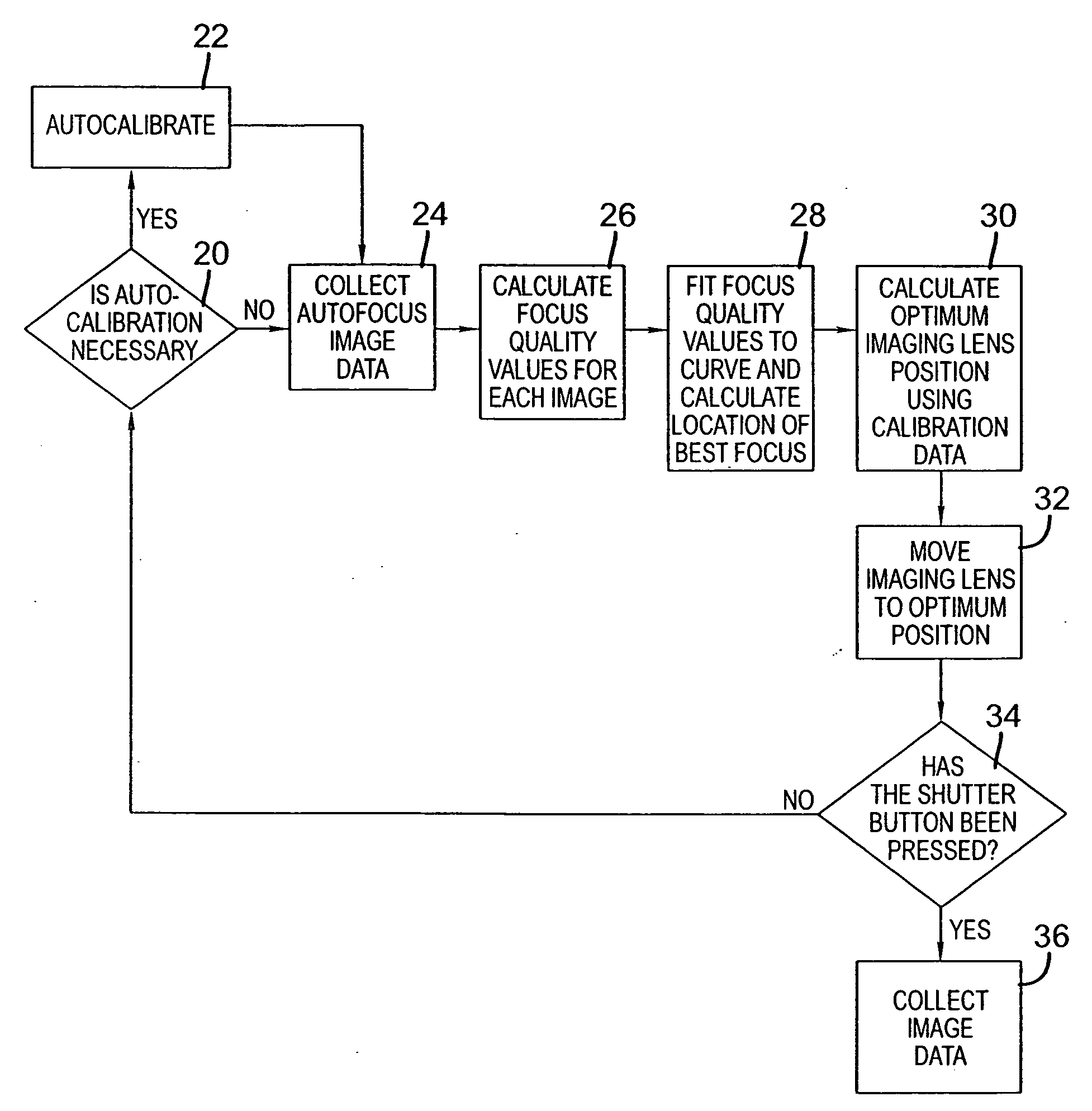
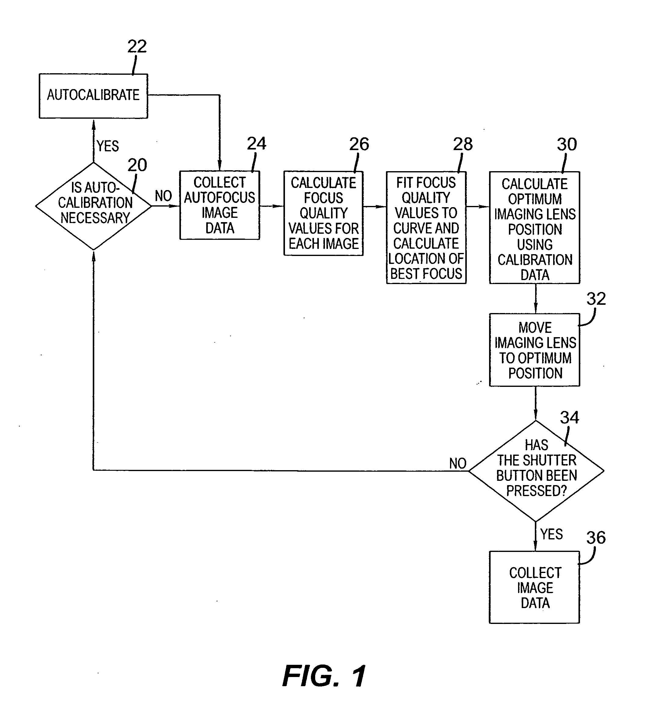
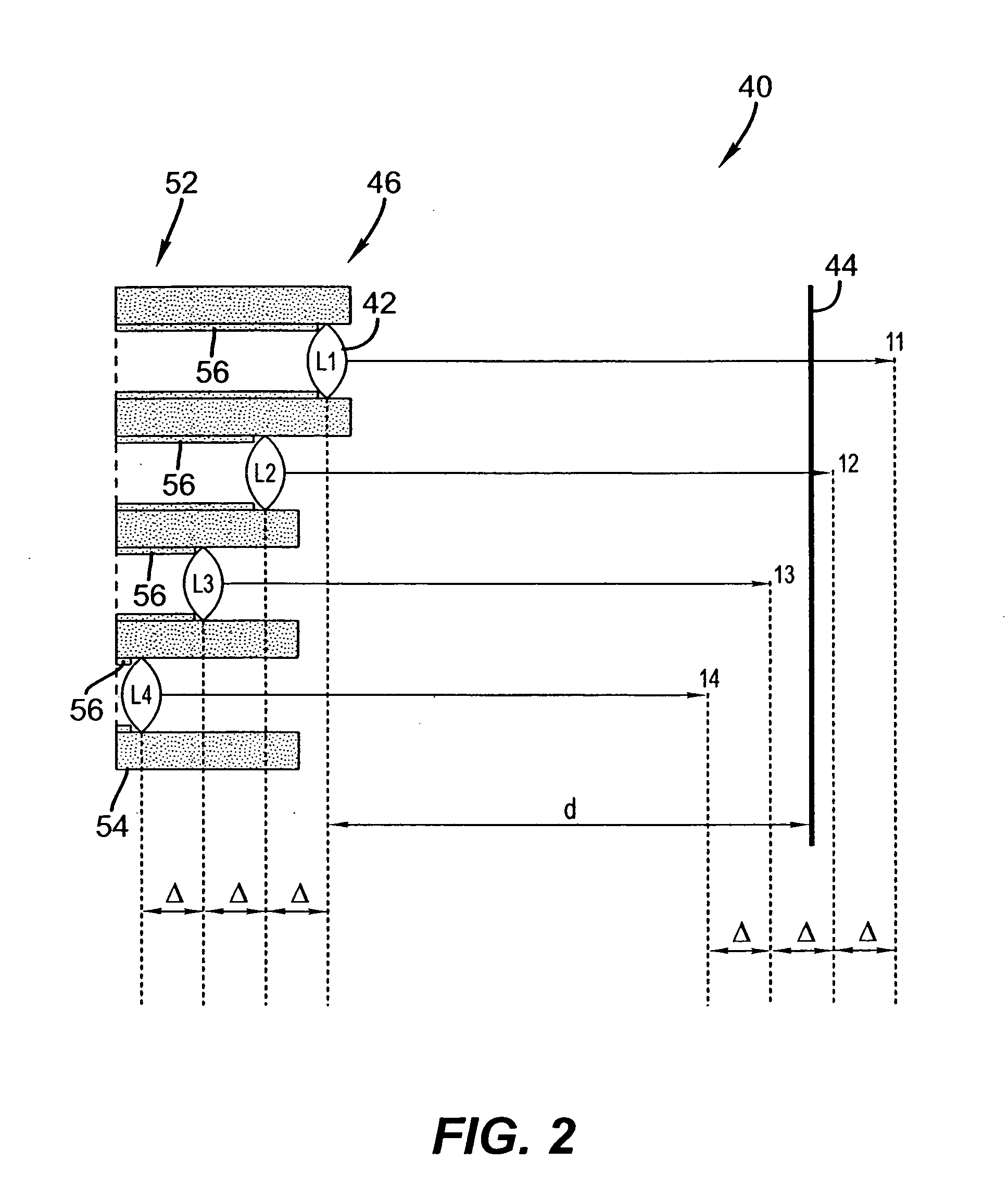
[0037]Referring to FIG. 1, a block diagram illustrating the basic sequence of events involved in autofocusing as it relates to the present invention is shown. Generally described, a method of detecting focus includes providing a plurality of images on a first image sensor by causing light to pass through a plurality of lenslets, each of the plurality of lenslets having a distinct conjugate length; determining relative focus quality by comparing the plurality of images to each other; and adjusting a distance between a taking lens and a second image sensor, the distance corresponding to a functional relationship between the conjugate lengths of the plurality of lenslets and the ...


PUM


Abstract

A focus detection device includes an image sensor and a plurality of lenslets. Each of the plurality of lenslets has a distinct conjugate length and is associated with a distinct portion of the image sensor.

Description

FIELD OF THE INVENTION[0001]The present invention relates generally to the use of a lenslet array to provide a series of low resolution images that can be used to guide an image capture device.BACKGROUND OF THE INVENTION[0002]Digital cameras photoelectrically convert the image of an object on an image sensor and store the image data in memory or the like. Focus detection devices for automatic focusing of digital still cameras usually rely on one of the following methods: Hill-Climbing focus detection; passive triangulation; active triangulation; phase difference detection; hybrid autofocusing; software focusing correction; and focus detection using a phase control plate and high frequency filters.[0003]In Hill-Climbing focus detection, the taking lens of an image sensing optical system is moved incrementally along the optical axis, and an image is acquired for each incremental lens position. Each of the acquired images are analyzed for focus quality (for example, contrast or sharpne...

Claims


Application Information

Patent Timeline
Patent Type & Authority Applications(United States)
IPC IPC(8): G03B13/00
CPCH04N5/23212G03B13/36H04N23/673
Inventor SCHILLING-BENZ, LYNNBORDER, JOHN N.POWERS, THOMAS F.PALUM, RUSSELL J.
Owner INTELLECTUAL VENTURES FUND 83 LLC
Why Eureka
Try Eureka