Dipole antenna

a technology of dipole antennas and antennas, applied in the direction of resonant antennas, antenna feed intermediates, radiating element structural forms, etc., can solve the problems of high difficulty level of process, bottleneck of performance improvement, and design limitations of conventional technology, so as to achieve excellent antenna features, wide bandwidth, and high antenna gain

Inactive Publication Date: 2005-10-18
ACCTON TECHNOLOGY CORPORATION
View PDF4 Cites 16 Cited by
  • Summary
  • Abstract
  • Description
  • Claims
  • Application Information

AI Technical Summary

Benefits of technology

[0008]Still another object of the present invention is to provide a dipole antenna for obtaining high antenna gain and broad bandwidth.
[0010]Hence, with the use of the present invention, the dipole antenna can be briefly merged into the entire electric circuit layout, and the purpose of impedance matching can be achieved, and the excellent antenna features of high antenna gain and broad bandwidth can be obtained as well.

Problems solved by technology

However, for the aforementioned conventional dipole antenna, the antenna performance can be promoted merely by focusing on the design of the length or thickness of the antenna electrodes, and the aforementioned technology still has quite a bottleneck for performance improvement.
Therefore, the conventional technology has quite a few design limitations and high difficulty level of process.

Method used


Image

  • Dipole antenna
  • Dipole antenna
  • Dipole antenna

Examples


Embodiment Construction

[0021]Hereinafter, the preferred embodiments of the present invention will be described in detail with reference to the accompanying drawings.

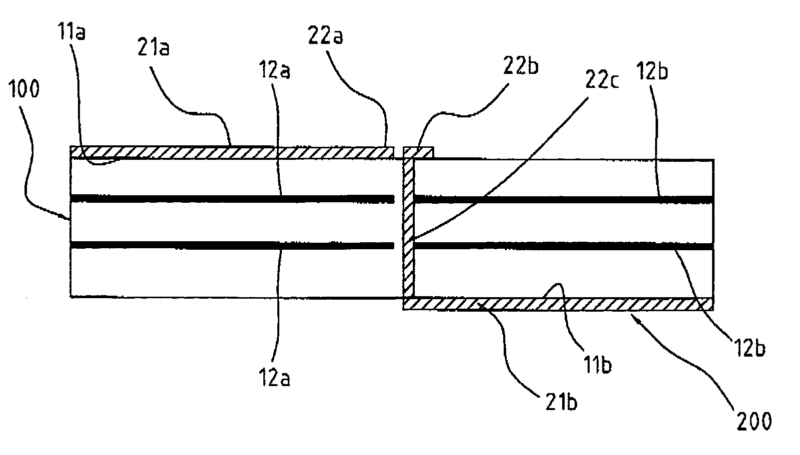
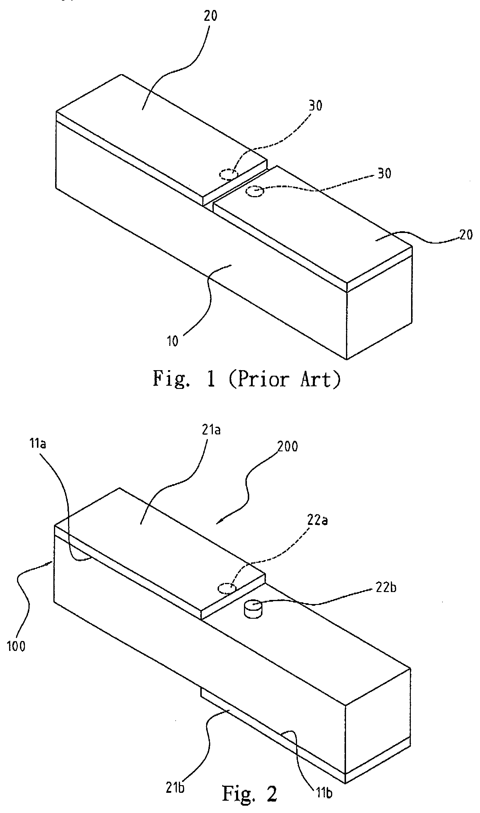
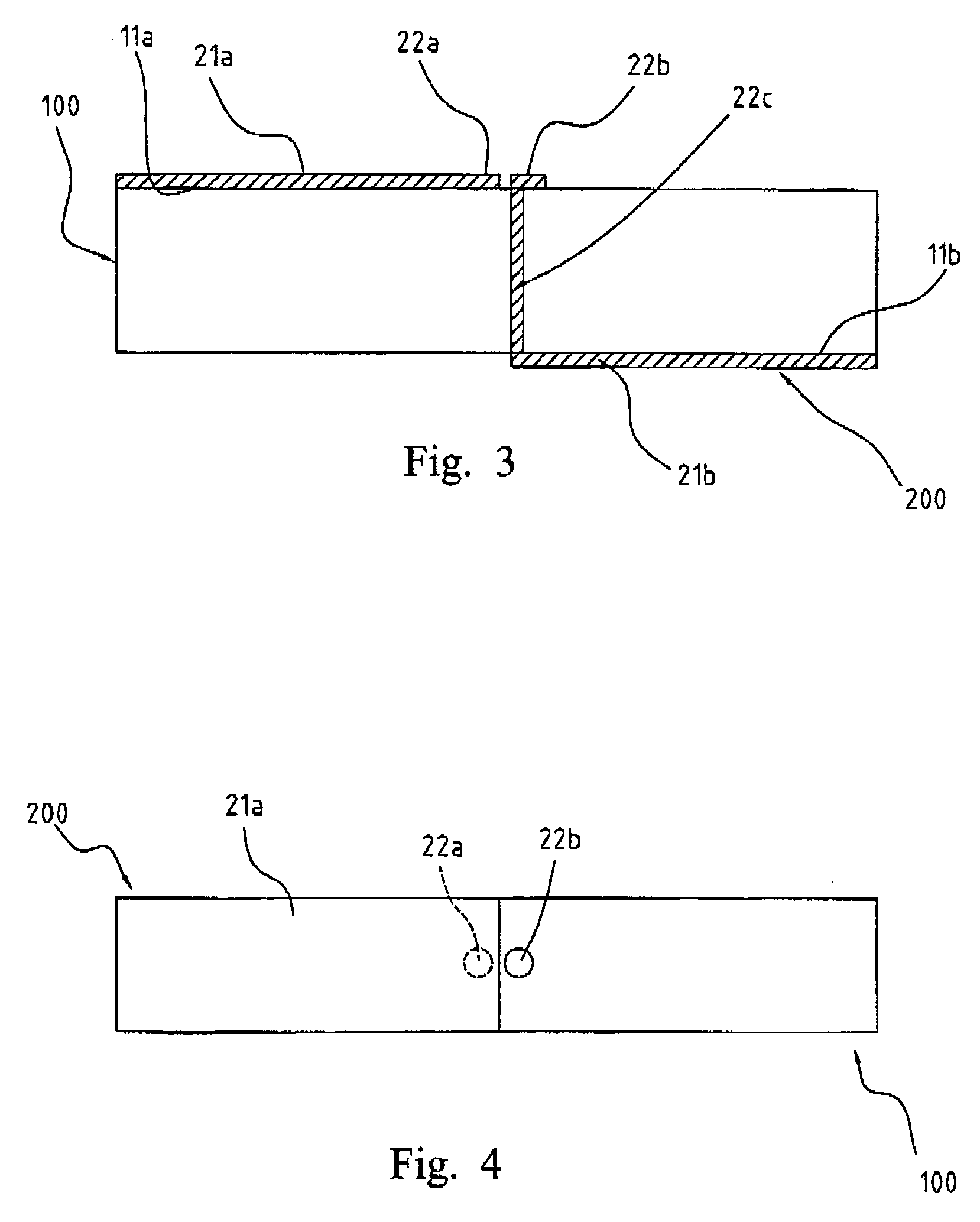
[0022]Referring to FIG. 2 to FIG. 5, FIG. 2 to FIG. 5 illustrate a dipole antenna, according to a preferred embodiment of the present invention, wherein the fundamental radiation structure of an antenna 200 is formed mainly by disposing a first radiator 21a and a second radiator 21b respectively on a first surface 11a and a second surface 11b of a substrate 100, and the first surface 11a is essentially parallel to the second surface 11b.

[0023]The substrate 100 is made of dielectric material, such as FR4, etc. The first radiator 21a and the second radiator 21b are formed by disposing electrically-conductive material respectively on the non-overlapped areas of the first surface 11a and the second surface 11b, such as on the left half portion of the first surface 11a and the right half portion of the second surface 11b. Further, a first feeding ...


PUM


Abstract

A dipole antenna is disclosed, and two electrodes thereof are respectively disposed on two surfaces of a substrate, wherein those two surfaces are parallel to each other. Metallic layers allocated in the substrate are used to control impedance match, and to promote the antenna gain and operation bandwidth of the dipole antenna.

Description

FIELD OF THE INVENTION[0001]The present invention relates to a dipole antenna, and more particularly, to the dipole antenna having two electrodes disposed respectively on two essentially parallel surfaces of a substrate.BACKGROUND OF THE INVENTION[0002]An antenna in the communication products is an element mainly used for radiating or receiving signals, and generally, the features of antenna are determined by the parameters of operation frequency, radiation patterns, reflected loss, and antenna gain, etc. According to different operation requirements, the functions equipped in the communication products are not all the same, and thus there are many varieties of antenna designs used for radiating or receiving signals, such as a dipole antenna, a rhombic antenna, a turnstile antenna, a triangular microstrip antenna, and an inverted-F antenna, etc.[0003]A conventional dipole antenna applied in a wireless transmission device generally is a straight-line-typed dipole antenna. Referring t...

Claims


Application Information

Patent Timeline
Patent Type & Authority Patents(United States)
IPC IPC(8): H01Q9/06H01Q9/28H01Q1/38H01Q9/04
CPCH01Q1/38H01Q9/065H01Q9/285
Inventor LEE, CHANG-JUNG
Owner ACCTON TECHNOLOGY CORPORATION
Why Eureka
Try Eureka