Electronic endoscope for highlighting blood vessel

a technology of endoscopy and electronic endoscopy, which is applied in the field of image processing of electronic endoscopy, can solve the problems of difficult differentiation between blood vessel b>3/b> and other tissue such as mucous membrane b>2/b>

Inactive Publication Date: 2005-10-18
FUJI PHOTO OPTICAL CO LTD
View PDF1 Cites 20 Cited by
  • Summary
  • Abstract
  • Description
  • Claims
  • Application Information

AI Technical Summary

Benefits of technology

[0006]By the way, image pickup targets of the electronic endoscope are often objects inside a living body such as digestive organs, and as shown in FIG. 13, a magnified object image 1 (displayed on a monitor, etc.) includes a blood vessel (capillary blood vessel) 3 in a mucous membrane 2 and a blood circulation state and a concentration situation of this blood vessel (blood) 3 constitute important observation targets in making a diagnosis of a focus or identifying cancerous ...

Problems solved by technology

On the other hand, since the interior of the living body has pink or reddish coloring, making a disti...

Method used


Image

  • Electronic endoscope for highlighting blood vessel
  • Electronic endoscope for highlighting blood vessel
  • Electronic endoscope for highlighting blood vessel

Examples


first embodiment

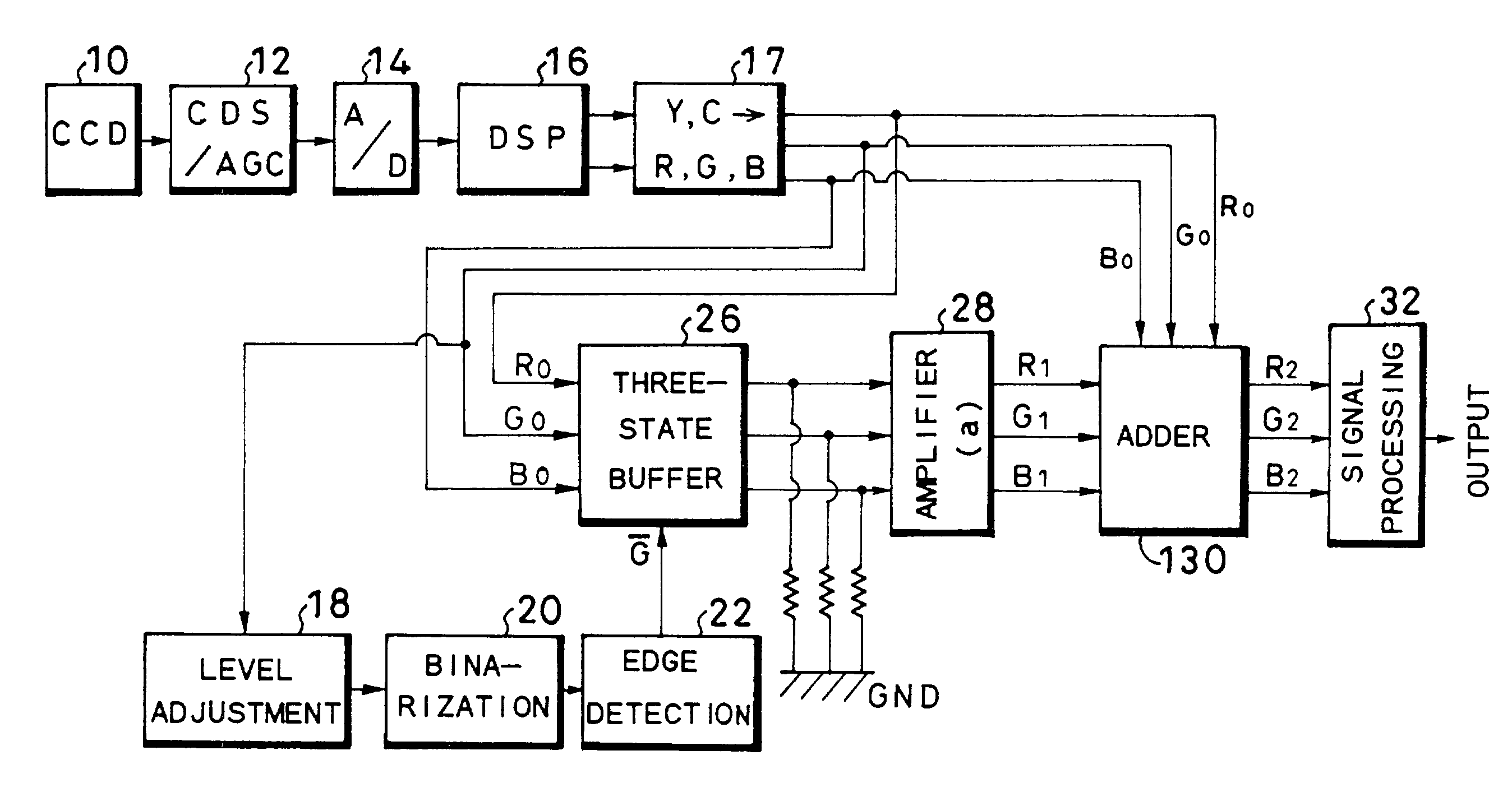
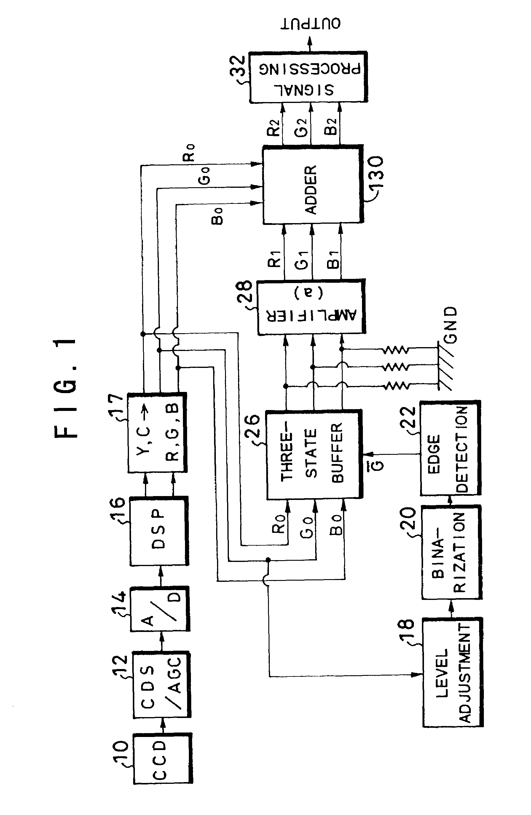
[0029]FIG. 1 shows a configuration of part of an electronic endoscope according to a first embodiment and this electronic endoscope is, for example, of a synchronous type and is provided with a scope, a processor unit, a light source unit, a monitor and a recorder, etc. In this FIG. 1, a CCD 10, an image pickup element, is provided at a tip of the scope and this CCD 10 captures an image of an object through color filters on a pixel-by-pixel basis (e.g., Mg (magenta), G (green), Cy (cyan) and Ye (yellow)). That is, when light from the above-described light source unit is irradiated from the tip of the scope onto the object through a light guide, the image of this object is taken by the CCD 10. Furthermore, if an objective optical system with a built-in power scaling movable lens is provided, in front of this CCD 10, it is possible to obtain a magnified image of the object by driving this power scaling lens.

[0030]The above-described CCD 10 is followed by a CDS (Correlated Double Sampl...

second embodiment

[0041]FIG. 3 shows a configuration of a second embodiment of the present invention and this second embodiment reduces the chroma of images other than those of blood vessels. That is, as shown in FIG. 3, an inverter 23 is inserted between an edge detection circuit 22 and three-stage buffer 26, which inverts the output of the edge detection circuit 22 and supplies the inverted output to the three-state buffer 26. This three-state buffer 26 is followed by an amplifier 29 whose amplification factor “a” ranges from 0 to 1 and a subtractor 31.

[0042]According to this second embodiment, signals (position signals) of images other than those of blood vessels are extracted through an inversion operation of the inverter 23, and thus signals R0, G0 and B0 making up images other than those of blood vessels are extracted from the three-state buffer 26 and the respective color signals are amplified at an amplification factor “a” (029. That is, the amplifier 29 outputs R3=aR0, G3=aG0 and B3=aB0. The...

third embodiment

[0044]FIG. 4 shows a configuration of a third embodiment of the present invention and this third embodiment displays thickened blood vessels. As shown in FIG. 4, in addition to the configuration of the first embodiment, the third embodiment provides a frequency division circuit 24 that divides a clock signal and generates a slower clock signal and a latch circuit 25 that latches R0, G0 and B0 signals making up a blood vessel image using the outputs of this slow clock signal and the edge detection circuit 22. That is, the above-described frequency division circuit 24 divides the clock signal (frequency f1) input by, for example, 2 and the above-described latch circuit 25 gives a latch signal for doubling the thickness of the blood vessel to the three-state buffer 26 through a clock signal with a double cycle (frequency (f1 / 2)) and blood vessel signal.

[0045]As in the case of the first embodiment, according to this third embodiment, the G0 signal output from the color conversion circui...


PUM


Abstract

The apparatus according to the present invention includes a level adjusting circuit that increases a gain of a G (or B) signal output from a color conversion circuit, a binarization circuit that forms a binarized image from this G signal and an edge detection circuit that extracts blood vessel position signals through edge detection based on this binarized signal. Then, the apparatus extracts RGB color signals making up a blood vessel image by using the above-described blood vessel position signals, increases the gains of these blood vessel color signals and then adds the blood vessel color signals to the color signals of an original image. This allows blood vessels to be displayed in high contrast to mucous membranes, etc. Furthermore, the apparatus can also amplify the R signal and B signal by using a signal obtained by differentiating the above-described G signal as a gain signal to highlight blood vessels.

Description

BACKGROUND OF THE INVENTION[0001]This application claims the priority of Japanese Patent Applications Nos. 2001-295272 and 2001-295273 filed on Sep. 27, 2001 and No. 2002-21076 filed on Jan. 30, 2002 which are incorporated herein by reference.[0002]1. Field of the Invention[0003]The present invention relates to an electronic endoscope, and more particularly, to image processing of an electronic endoscope capable of displaying details of capillary blood vessels, etc. inside a body of an examinee.[0004]2. Description of the Related Art[0005]An electronic endoscope irradiates an object under observation with illuminating light to capture an image thereof through an objective optical system, takes in the image using an image pickup element such as a CCD (Charge Coupled Device) and displays this object image on a monitor, etc. In recent years, this type of electronic endoscope incorporates a power scaling mechanism in the above-described objective optical system and displays the opticall...

Claims


Application Information

Patent Timeline
IPC IPC(8): H04N7/18A61B1/04A61B1/045
CPCH04N7/183A61B1/00009A61B1/045A61B1/0638A61B1/000094
Inventor HIGUCHI, MITSURUAYAME, DAISUKEABE, KAZUNORITAKEUCHI, SHINJINEGISHI, KEIICHI
Owner FUJI PHOTO OPTICAL CO LTD
Why Eureka
Try Eureka