Compact optical delay lines

a delay line and compact technology, applied in the field of communication systems, can solve problems such as interference between light signals applied at the two inputs

Inactive Publication Date: 2005-10-18
MAIN STREET VENTURES
View PDF27 Cites 28 Cited by
  • Summary
  • Abstract
  • Description
  • Claims
  • Application Information

AI Technical Summary

Benefits of technology

[0043]An all-optical system for modulating, switching, multiplexing, demultiplexing, and routing signals, for example digital signals in an optical medium, employs control units that direct energy according to a coincident control signal which may be in the same form as the digital signal. Briefly, in an embodiment where the signals are optical, any of a variety of different interactions between light inputs results in a combined output with a different magnitude when both inputs coincide than when they do not. For example, an energy summer produces an output whose power is proportional to the sum of the two inputs when the two inputs coincide and whose power is proportional to the individual inputs when the two inputs do not coincide. In an example embodiment, a control signal determines the power level of the output based on some addressing technique by combining the control signal at one input with a data signal at the other input. The control and the data signals may arrive from the same source of from different sources. The resulting signal has a higher magnitude when control and data signals are combined than when not. The output may be received by an optical-electrical transducer (e.g., a photodiode circuit) or an all optical threshold device configured to discriminate signals above a predefined threshold (electronically or optically) from signals below the predefined threshold. In such a receiver, data signals that are summed with a control signal are accepted as received data, while signals that are not summed (and, as a result, having a power magnitude below the threshold) are rejected. In an application of this example using a summer, a transmitter modulates a light beam to form pulses, each representing a bit consisting of a data pulse and a control pulse whose spacing represents a destination address. The modulated beam is applied in parallel to a set of summers. Each summer has a non-delayed input and a delayed input (or two inputs when each input has a different delay). Each summer has a respective delay at its delayed inputs (or between its inputs) such that a given spacing between the data and control pulses causes a coincidence at only one of the summers. The outputs of all the summers are sent to respective receivers, each configured to reject signals whose magnitude is below a specified threshold. Only one receiver will accept the data pulses “addressed” for the gate (i.e. whose spacing corresponds to that gate's control input's delay) connected to that receiver. In this embodiment, pulse-pairs will produce a single output pulse whose magnitude meets a threshold only at a single receiver. This function results in, effectively, a routing of each data bit to a selected receiver over a channel connected to multiple receivers.
[0053]Combined modulation can be achieved by any combination of the modulation methods, i.e., time, phase, and polarization. A combination of modulation methods increases the number of independent parameters that each symbol contains and thus increases the amount of information that each symbol can carry.
[0056]An alternative device for producing a coincidence effect is to perform non-coherent summing. Laser light from a multimode laser or a Light Emitting Diode (LED) characterized by a distribution of wavelengths and / or phases can be modulated and summed non-coherently. In such an embodiment, the ratio of energies of the coincidence output and the non-coincidence outputs may not be as high as with coherent summing, but the effect is still strong enough to be usable for gating.
[0072]In another version, the present invention provides an optical delay line for delaying optical signals and optical phases including a core of an open loop of a radiation guide forming a pair of radiation waveguide connected in one of their edges and turned around the core of the opened loop.

Problems solved by technology

In these embodiments, the interaction is coherent resulting in interference between the light signals applied at the two inputs.

Method used


Image

  • Compact optical delay lines
  • Compact optical delay lines
  • Compact optical delay lines

Examples


Embodiment Construction

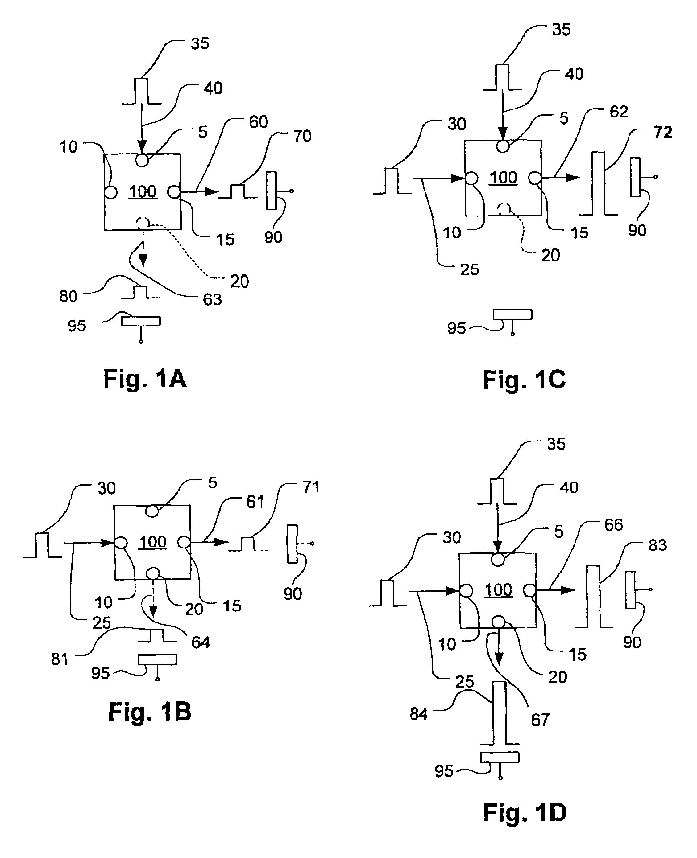
[0155]FIGS. 1A, 1B, 1C and 1D are figurative illustrations of a gate 100 that directs applied energy, for example, optical energy, based on an interaction between two sources, such as a control source and a source representing data. As discussed below, the gate 100 may permit the selective application of higher energy to an output port based on the timing and configuration of inputs by interaction of the inputs and without the requirement for a state change of the gate 100. A discussion of various embodiments that exhibit this behavior follows the discussion of FIGS. 1A, 1B, 1C and 1D.

[0156]Referring to FIG. 1A, a gate 100 has two inputs 5 and 10 and is configured such that when compatible energy signals are received simultaneously at the inputs 5 and 10, responsive outputs, at an output port 15, is obtained. For example, the inputs may be optical energy pulses whose phases are aligned to constructively interfere within the gate 100 or light beams whose polarization angles are in a ...


PUM

PropertyMeasurementUnit
time responseaaaaaaaaaa
reflectanceaaaaaaaaaa
optical delayaaaaaaaaaa

Abstract

The present invention provides an optical delay, for example, an optical delay line, having at least first and second waveguides, each waveguide having a first end at a first side of the device and a second end at a second side of the device, wherein the second end of the first waveguide is coupled to the second end of the second waveguide at a reflective coupling region, which reverts the direction of propagation of radiation in the device from propagating towards the second side of the device via the first waveguide to propagating towards the first side of the device via the second waveguide.

Description

REFERENCE TO OTHER APPLICATIONS[0001]This application claims the benefit of U.S. Provisional Patent Application Ser. No. 60 / 405,697, filed Aug. 22, 2002, entitled “Streaming signal control system for digital communications”, and of U.S. Provisional Patent Application Ser. No. 60 / 420,112, filed Oct. 21, 2002, entitled “Streaming signal control system for digital communications”.FIELD OF THE INVENTION[0002]The invention relates to communications systems and more particularly to the modulation and control of signals for example by interaction of energy in a stateless controller device.BACKGROUND AND PRIOR ART[0003]In the field of optical communication, there is a pressing need to improve the capacity of optical networks and the speed of switching at reasonable cost. These are attended by the related problems of efficient retrofit to existing infrastructure, ease of maintenance, reliability, etc. The physical media of optical fibers used in current generation optical networks have a tre...

Claims


Application Information

Patent Timeline
Patent Type & Authority Patents(United States)
IPC IPC(8): G02B6/28G02B6/125H04B10/17G02B6/12G02B6/34G02B6/04H04J14/02H04J14/08G02F1/35
CPCG02B6/125G02B6/2861H04B10/299G02B6/04G02B6/2804G02B6/2821G02B2006/12107G02B2006/12142G02B2006/12145G02B2006/12147G02B2006/1215G02B2006/12164G02F1/3521H04J14/02H04J14/08
Inventor SHAHAR, ARIEHALBERTHAL, ELDAN
Owner MAIN STREET VENTURES
Why Eureka
Try Eureka