Method and system for monitoring a molding machine

Inactive Publication Date: 2005-10-25
SINTOKOGIO LTD
View PDF10 Cites 14 Cited by
  • Summary
  • Abstract
  • Description
  • Claims
  • Application Information

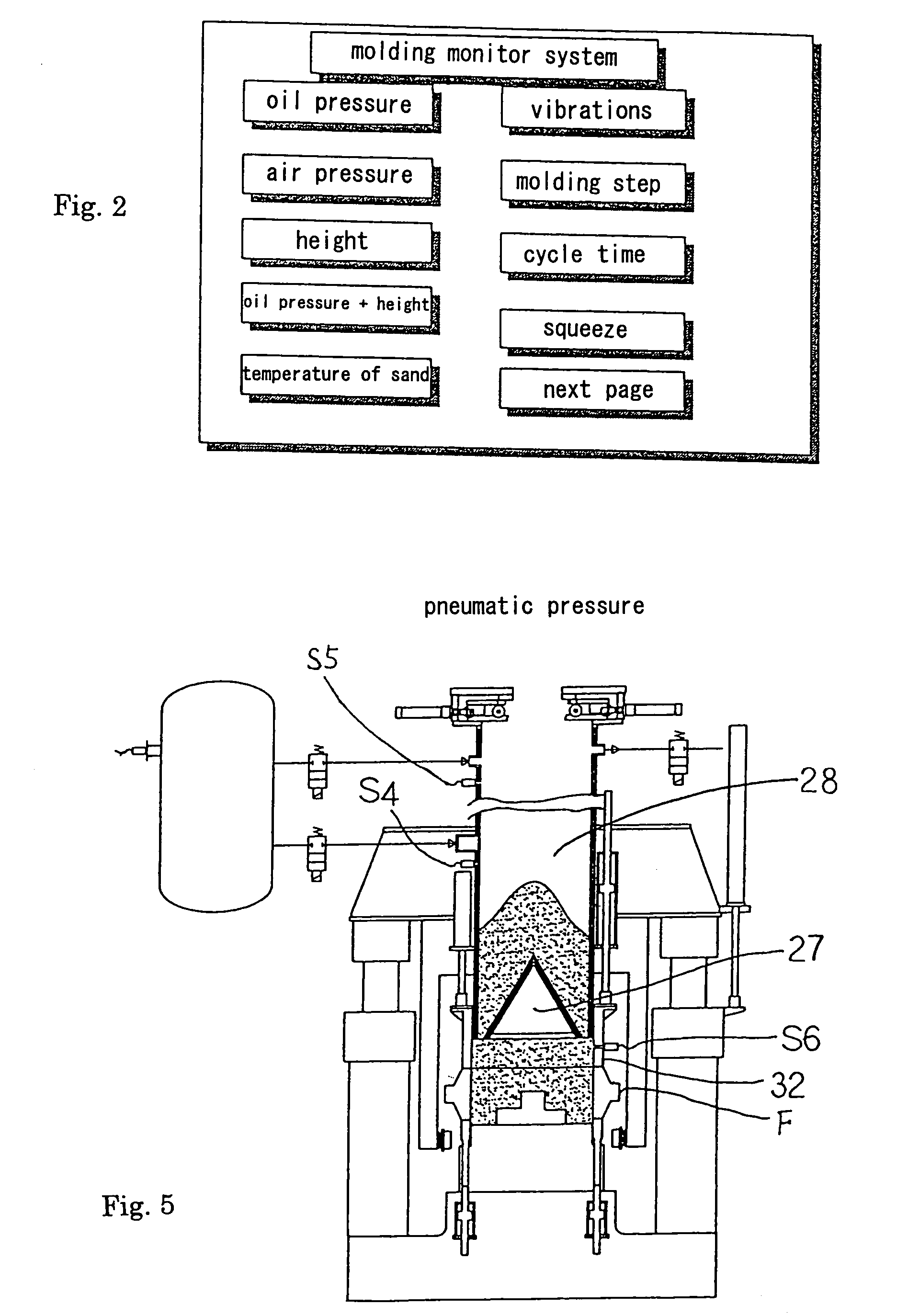
AI Technical Summary

Benefits of technology

[0012]For a further example, since the data on the pressures of the aeration, the auxiliary air, and the air in the flask are collected from the molding machine when it operates, the relationship between a produced mold and the pressures can be obtained, and thus a proper value for each oil pressure can be set or such a value may be modified. Further, since these pressures are displayed, one can easily repair an abnormal operation. This allows the machine to stably work to produce a product of a good quality.
[0013]For a further example, since the data on the positions of the frame-setting cylinders and the filling-frame cylinders are obtained by using encoders from the molding machine when it operates, the relationship between a produced mold

Problems solved by technology

However, there is no means to check whether the elements are normally working, and usually a checker examines by his or her senses the elements, or actuating means, that work abnormally or that has come not to work.
Accordin

Method used


Image

  • Method and system for monitoring a molding machine
  • Method and system for monitoring a molding machine
  • Method and system for monitoring a molding machine

Examples


first embodiment

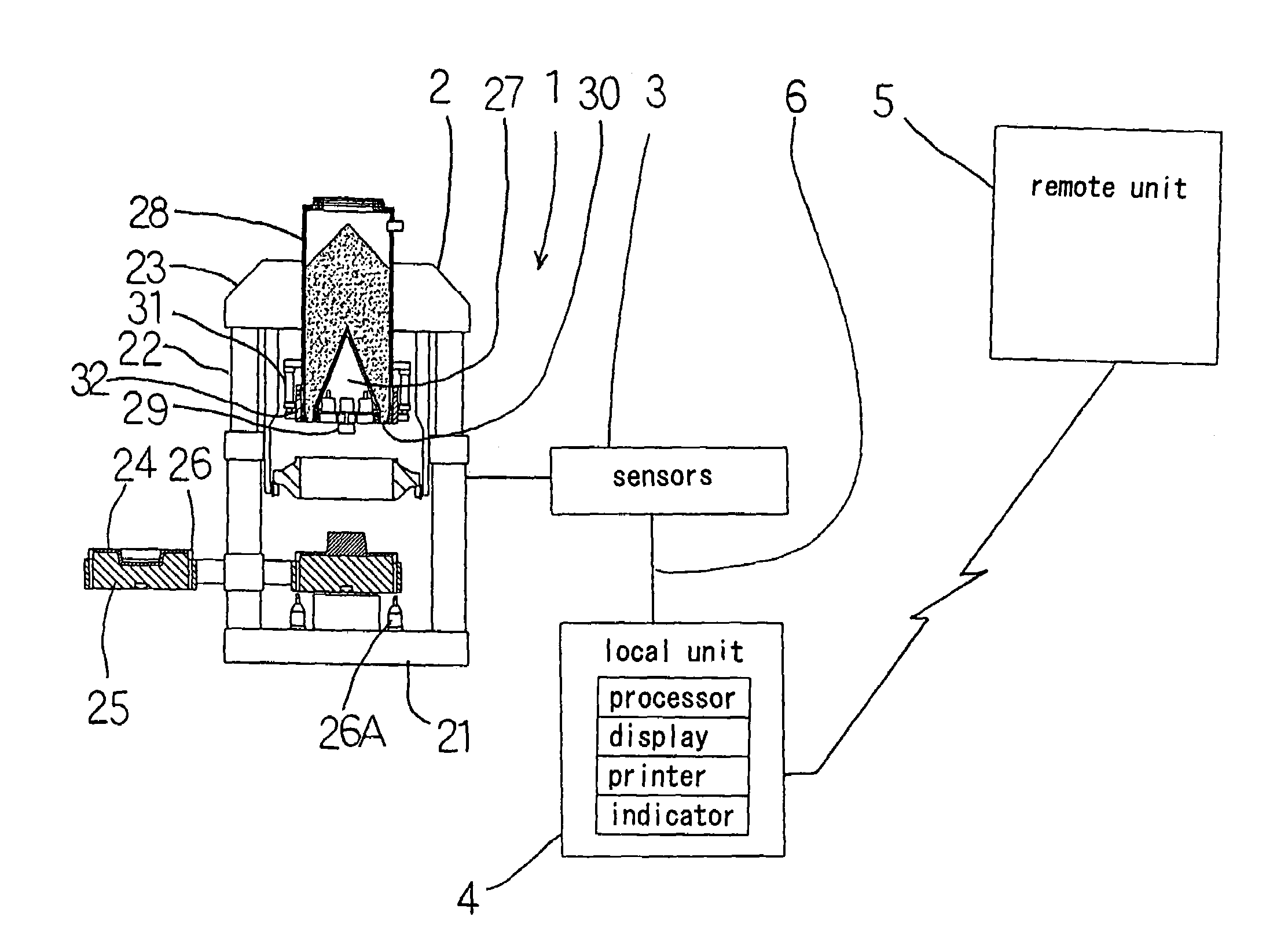
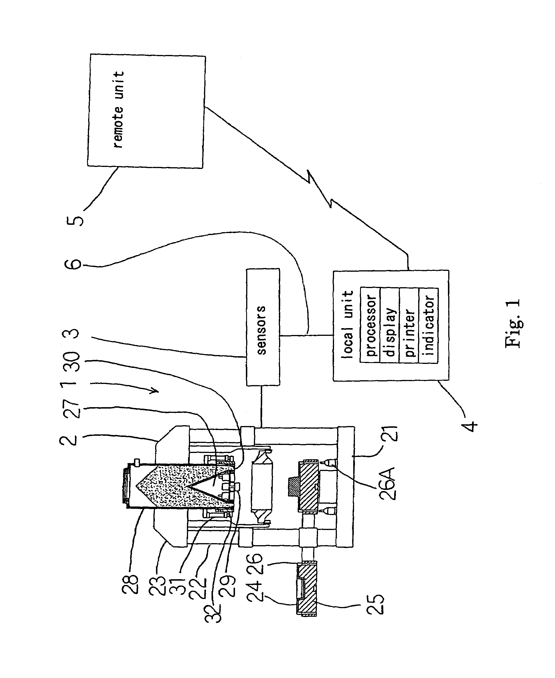
[0046]FIG. 1 shows a schematic structure of a molding machine and hardware of the embodiment of the present invention. A molding monitor system 1 of the embodiment of the invention shown in FIG. 1 is provided with some kinds of sensors 3 for measuring or detecting attributes of a molding machine 2. The sensors 3 are connected via a signal wire or wires 6 to a local unit 4, which in turn is connected to a remote unit 5.

[0047]The molding machine 2 of the embodiment of the present invention includes a molding base 21, frame-setting cylinders 22 mounted on the base 21 at the right and left thereof, a vertically-movable supporting frame 23 installed across the upper ends of the frame-setting cylinders 22, a pattern carrier 25 that carries a pattern plate 24 to a place above the central portion of the molding base 21, an annular leveling frame 26 for surrounding the pattern plate 24 located above the base 21 and for vertically sliding along the sides of the pattern plate 24, a flask F sus...

second embodiment

[0059]Another embodiment of the present invention is now explained by reference to some drawings. In FIGS. 1 and 3 the local unit 4 is provided with sensors for detecting the attributes on the squeeze of the molding machine 2. These sensors are pressure sensors S1, S2, and S3 for detecting the pressure of the working fluid of the frame-setting cylinders 22, filling-frame cylinders 21, and cylinders 26A for actuating the leveling frame 26, respectively. All other arrangements are similar to the first embodiment.

[0060]The operation of the second embodiment is now explained. In the molding monitor system 1 the monitor function for the oil pressure may be selected from many functions (FIG. 2) in the screen of the remote unit 5. When the molding machine 2 is operating, the monitor function for the oil pressure displays the detected values from the sensors S1, S2, and S3 for the frame-setting cylinders 22, filling-frame cylinders 21, and cylinders 26A for the leveling frame 26.

[0061]FIG. ...

third embodiment

[0064]Below another embodiment of the present invention is explained by reference to some drawings.

[0065]In FIGS. 1 and 5 the local unit 4 has sensors 3 for detecting pneumatic pressures of the molding machine. The sensors 3 are sensors S4, S5, and S6 for detecting the pressure of the air of the aeration from the central portion of the sand hopper 28 or air-jet chamber 27, the pressure of the auxiliary air from the upper part of the sand hopper 28, and pressure of the air in the flask F or filling-frame 32, respectively. All other arrangements are similar to the first embodiment.

[0066]The operation of the third embodiment is now explained. The remote unit 5 of the molding monitor system 1 can select the function for air pressure (pneumatic pressure) from its many monitor functions. When the molding machine 2 operates, the monitor function for the pneumatic pressure sends the signals from the pressure sensors S4, S5, S6 (sensors 3) to the local unit 4, which sensors detect the attrib...


PUM

PropertyMeasurementUnit
Pressureaaaaaaaaaa

Abstract

A monitor system for monitoring a molding machine that includes a vertically-movable supporting frame, a pattern carrier on which a pattern is placed, a flask placed on a leveling frame, a sand hopper provided with an optional an air-jet chamber, sand-charging nozzles disposed around a plurality of squeeze feet that is disposed at a lower end of the sand hopper, and a filling frame connected to filling-frame cylinders and surrounding the squeeze feet and the sand-charging nozzles from their outside, the filling frame to be placed on the flask when lowered, comprising at least one sensor connected to the molding machine, for detecting an attribute of the molding sand as required and data analyzing monitor means connected to the sensor, for receiving data that correspond to the attribute detected by the sensor and analyzing the attribute and displaying the results of the analysis.

Description

FIELD OF THE INVENTION[0001]This invention relates to a method and a system for monitoring a molding machine. The method and system of the invention includes a method and a system for monitoring a molding machine, wherein the method and system can receive and send data on the molding of the molding machine via a communication network.DESCRIPTION OF THE PRIOR ART[0002]WO 01 / 32333 A1 discloses a molding machine for producing a sand mold contained in a flask by executing primary squeeze and secondary squeeze using a leveling frame, which is vertically movably disposed around the pattern plate.[0003]The molding machine includes a vertically-movable supporting frame installed across the upper ends of upright, frame-setting cylinders mounted on the machine base, a pattern carrier for carrying a pattern thereon to a place above the machine base, an annular, vertically slidable leveling frame surrounding the sides of the pattern plate, a flask to be placed on the leveling frame, a sand hopp...

Claims


Application Information

Patent Timeline
IPC IPC(8): B22C15/00B22C19/00B22C19/04B22C15/24B22C15/28
CPCB22C15/24B22C15/28B22C19/04
Inventor HIRATA, MINORUHADANO, YUTAKASAKAI, TSUYOSHIMIZUNO, KENJI
Owner SINTOKOGIO LTD
Why Eureka
Try Eureka