
Patient care and communication system

a communication system and patient technology, applied in the field of patient care and communication system, can solve the problems of increasing the stress on the nursing staff, the task of performing, and the approaching of information overload, and achieve the effect of facilitating visual and data communication

Inactive Publication Date: 2005-10-25
HILL ROM SERVICES
View PDF108 Cites 235 Cited by
  • Summary
  • Abstract
  • Description
  • Claims
  • Application Information

AI Technical Summary

Benefits of technology

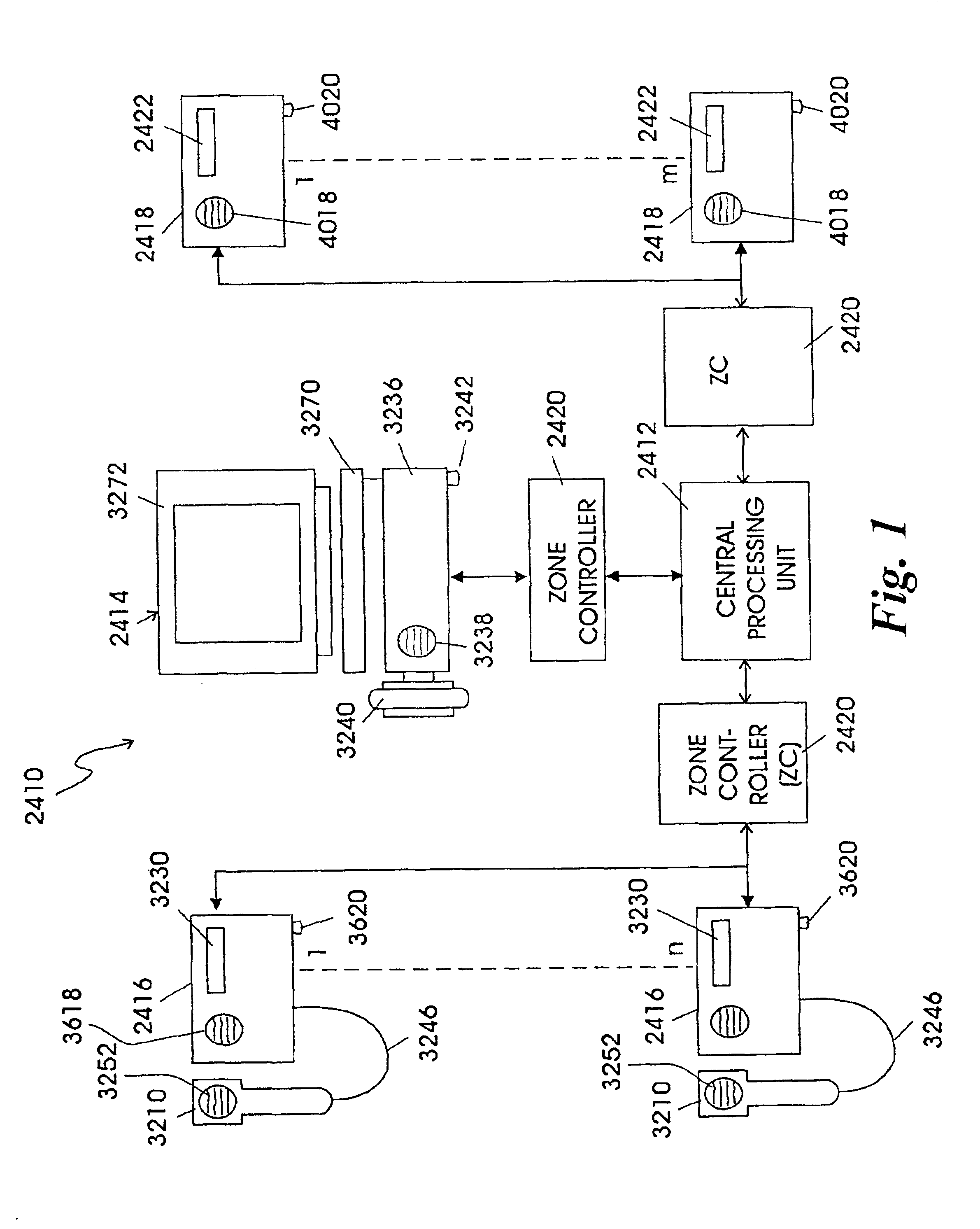
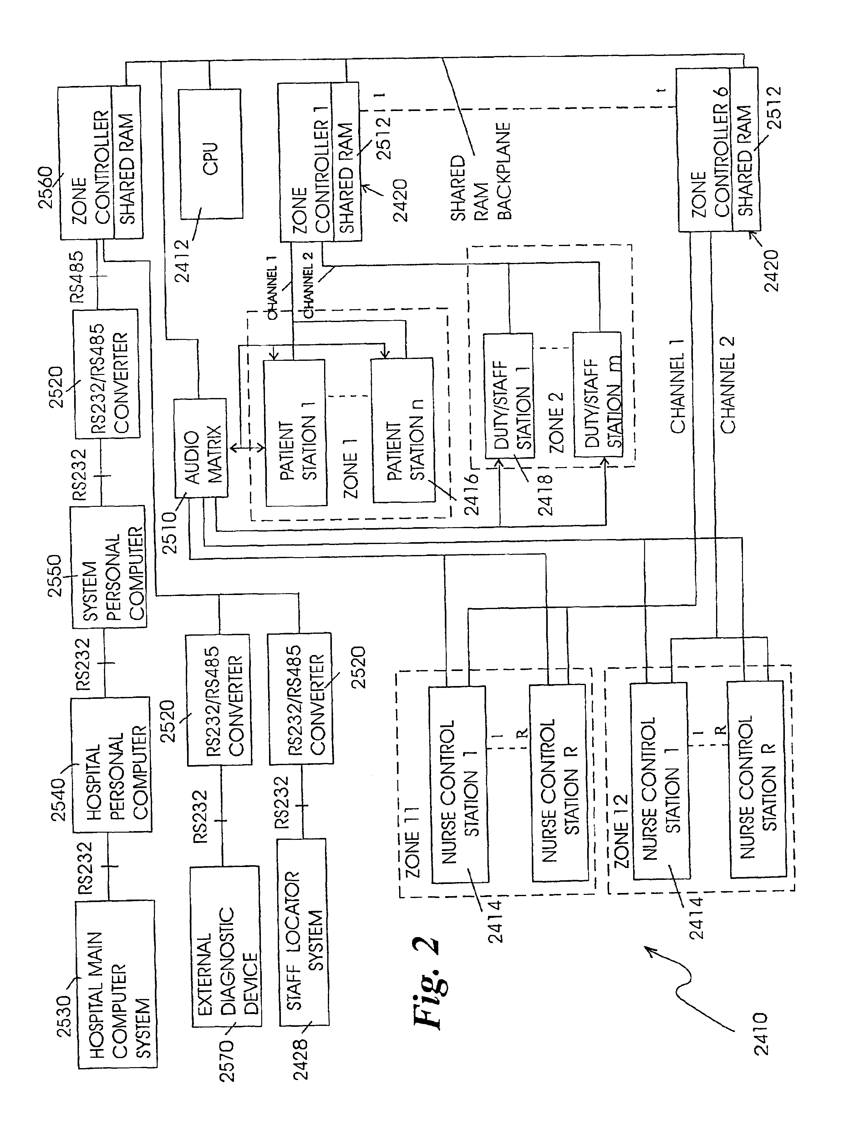
[0020]In the preferred embodiment, the central station also includes means for controlling the private-branch exchange to establish audio communication between a predetermined number of control stations, a predetermined number of the patient stations and a predetermined number of the staff stations.
[0021]The patient stations of the present invention include patient control means which is connected thereto and provide a remote communication link between the patient and staff members or the patient and outside callers. The patient control means has a keypad, a speaker and a microphone for telephone communications to other stations or for external telephone communications. It should be noted that external communications includes telephone communications from within the hospital environment to locations outside the hospital environment, generally via public telephone lines.
[0022]The system of the present invention also relates to a method of providing patient care and communication between patient rooms and nurse stations in a health care facility. The method includes the steps of connecting a plurality of remote stations to a central station so as to facilitate visual and data communications therebetween, and connecting each remote station and the central station to a private-branch exchange for audio communications between the remote stations. At least one of said plurality of remote stations is positioned in each patient room located within the health care facility, positioning at least one of said plurality of remote stations in each nurse station of said health care facility, attending the remote station in each nurse station to receive the visual and data signals from said central station and the audio signals from the PBX and responding to the audio, visual and data signals.

Problems solved by technology

Often, these tasks have to be performed even though there are personnel shortages.
As a result, stress on the nursing staff has increased and information overload is fast approaching.
Furthermore, such electronic systems do not provide visual displays of text at stations provided in the patient's room, at the nurse control station or at stations provided in areas of the health care facility frequently occupied by the health care personnel.
Another problem faced by care givers and by hospital administrators is determining the location of key personnel and equipment.
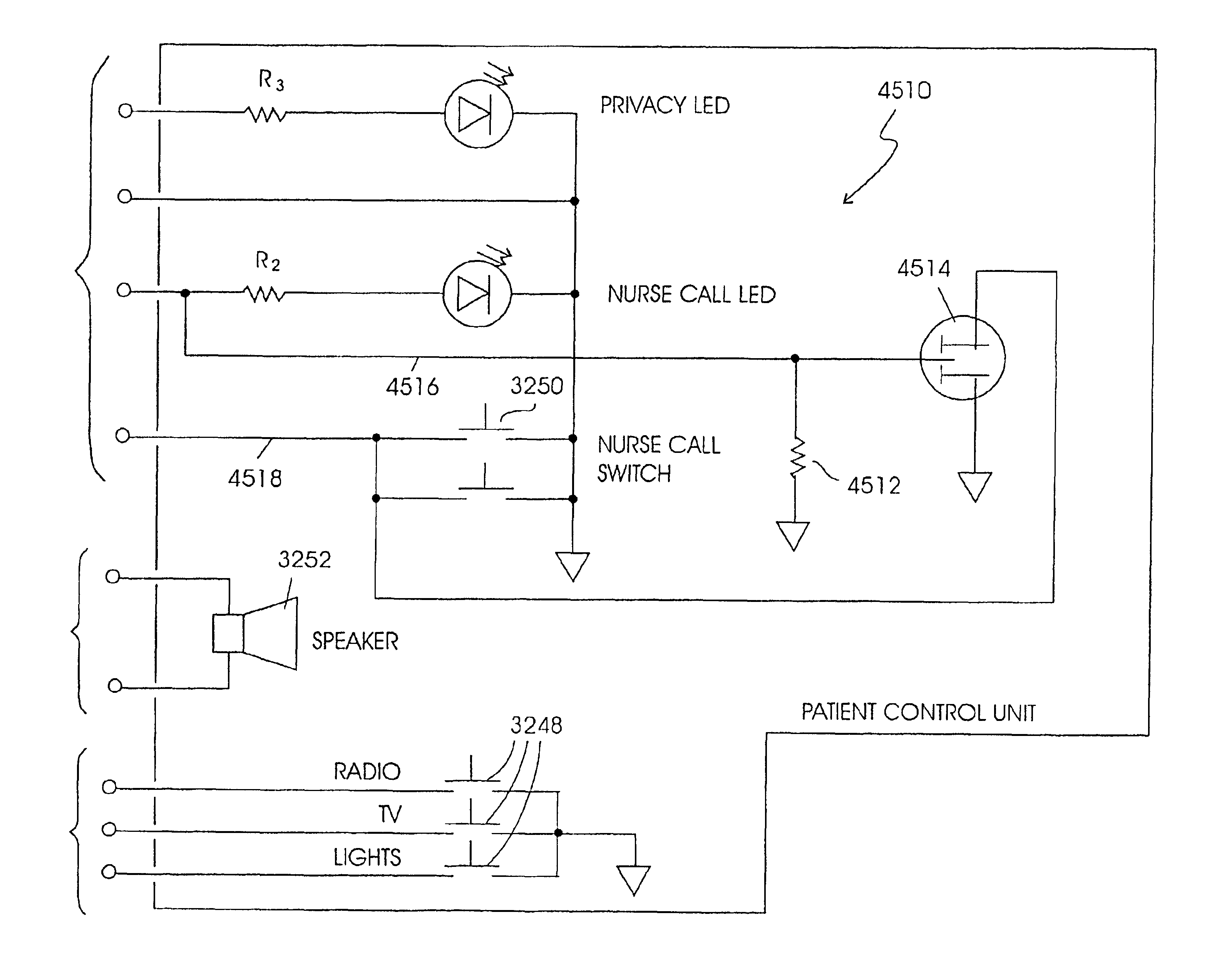
This system may not be effective if the person to be located is in an area where the paging system is not functioning properly or has been turned down, or if the person has left the hospital.
If, however, the person to be located forgot to use the sign-in sheet or sign-out sheet, critical time may be lost in a second attempt to use the audio paging system.
In addition, a search of the sign-in and sign-out sheets may require more time than is available in an emergency situation.
Each of these systems is limited in the type of information that may be conveyed between the stationary transceiver network and the transceiver on the badge.
Furthermore, if the transceiver on the badge fails or is damaged, a blank badge must be programmed to take its place.
This program operation may be time consuming, leaving the individual or the piece of equipment invisible to the locating system for that period of time.

Method used


Image

  • Patient care and communication system
  • Patient care and communication system
  • Patient care and communication system

Examples


Embodiment Construction

[0059]Generally, the patient care and communication system of the present invention includes a communication network that provides routine and emergency signaling to health care facility staff members and provides high fidelity voice communication and data transmission between staff members in the health care facility and / or between patients and the staff members.

[0060]The exemplary embodiments of the automatic staff locator system of the patient care and communication system of the present invention described below, use a memory card as a personal database. As used herein, a memory card is a device approximately the same size and shape as an ordinary credit card which includes a non-volatile programmable memory. In the card used in the embodiments described below, two types of memory are used: an electronically erasable read only memory (EEROM) located internal to the card and a magnetic stripe located on the surface of the card. It is contemplated, however, that other forms of int...


PUM


Abstract

The present invention relates to a patient care and communication system which utilizes a central processing system and a plurality of remote stations electrically connected to the central processing system to facilitate visual and data communications. Each remote station includes telephone circuitry which is connected to a private branch exchange for telephone communications between stations. In addition, the private branch exchange is connected to a telephone exchange and a plurality of telephones for facilitating telephone communication therebetween. The central processing system facilitates the visual and data communications between the plurality of remote stations, and includes a system for determining which of the plurality of remote stations are transmitting the visual and data communications and which of the plurality of remote stations are to receive the visual and data communications. The central processing system also includes a system which establishes a communication link between the transmitting stations and the receiving stations. The remote stations include a processing system which also facilitates the visual, data and telephone communications and a display for displaying the visual communications. The present invention also includes a staff and / or patient locator system, in which each remote station includes an infrared receiver that receives infrared transmissions from a portable transmitter worn by a staff member or patient. The infrared transmissions include identity information associated with the person wearing the transmitter. The identity information is then transferred to the central processing system which determines the identity and location of each person wearing a portable transmitter.

Description

CROSS REFERENCE TO RELATED APPLICATION[0001]This is a continuation of application Ser. No. 08 / 923,227, filed Sep. 4, 1997 now U.S. Pat. No. 6,259,355, which is a continuation-in-part of application Ser. No. 08 / 087,394, filed Jul. 2, 1993 now U.S. Pat. No. 5,455,851, and is a continuation-in-part of application Ser. No. 08 / 033,287, filed Mar. 16, 1993 abandoned, which is a continuation-in-part of application Ser. No. 07 / 924,101, filed Aug. 3, 1992 now U.S. Pat. No. 5,465,082, which is a continuation-in-part of application Ser. No. 07 / 559,196 filed on Jul. 27, 1990 now U.S. Pat. No. 5,291,399.BACKGROUND OF THE INVENTION[0002]1. Field of the Invention[0003]The present invention relates to a patient care and communication system which incorporates telephone communication therein. The system utilizes a PBX to provide staff-to-staff, staff-to-patient and / or external telephone communications. The system is also capable of performing tasks such as monitoring medical equipment in patient roo...

Claims


Application Information

Patent Timeline
Patent Type & Authority Patents(United States)
IPC IPC(8): G07C9/00G08B5/22G06F19/00G08B3/10G08B3/00H04M11/02
CPCG06F19/327G06F19/3418G06F19/3425G06K7/10079G07C9/00111G08B3/1083G08B5/222H04M11/027Y10S128/903G16H40/20G16H40/67G16H80/00G07C9/28
Inventor CHACO, JOHNHERSH, ISRAELORLOVSKY, DMITRYVINCENS, JOERAM, YARON
Owner HILL ROM SERVICES
Learn More