
Liquid crystal display device

a display device and liquid crystal technology, applied in the direction of identification means, instruments, non-linear optics, etc., can solve the problems of conspicuous reduced brightness, and reduced brightness, so as to achieve sufficient auxiliary capacitance and high aperture ratio, without deterioration of display quality

Inactive Publication Date: 2005-10-25
SHARP KK
View PDF3 Cites 1 Cited by
  • Summary
  • Abstract
  • Description
  • Claims
  • Application Information

AI Technical Summary

Benefits of technology

[0016]Therefore, it is an object of the present invention to provide a liquid crystal display apparatus that allows a sufficient auxiliary capacitance and a high aperture ratio to be obtained at the same time, without causing deterioration of display quality even when the definition is increased.

Problems solved by technology

However, as the definition or resolution of images increases, it becomes increasingly difficult to allow the scanning lines, the signal lines, and the auxiliary capacitor electrode to have a fine structure respectively.
Thus there will rise a problem that a light transmission area, namely, an aperture ratio decreases, which results in reduction of brightness.
However, the design invites the orientation disorder of the liquid crystal in the periphery of the pixel electrode, which causes conspicuous deterioration of the display quality.
Consequently optical leak is generated in the periphery of the pixel electrode 59, which deteriorates the display quality of the image greatly.
However, such a method results in decrease of the aperture ratio.
On the other hand, increase of the thickness of the auxiliary capacitor insulation film allows decrease of the influence of the electric field from the auxiliary capacitor electrode, but leads to decrease of the auxiliary capacitance.
Therefore the auxiliary capacitance cannot be secured sufficiently.

Method used


Image

  • Liquid crystal display device
  • Liquid crystal display device
  • Liquid crystal display device

Examples


first embodiment

(First Embodiment)

[0058]The liquid crystal display apparatus of the present invention will be described in detail below by way of examples.

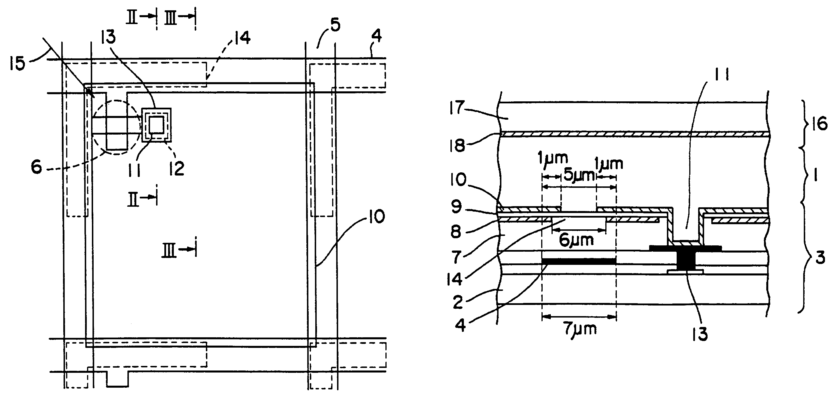
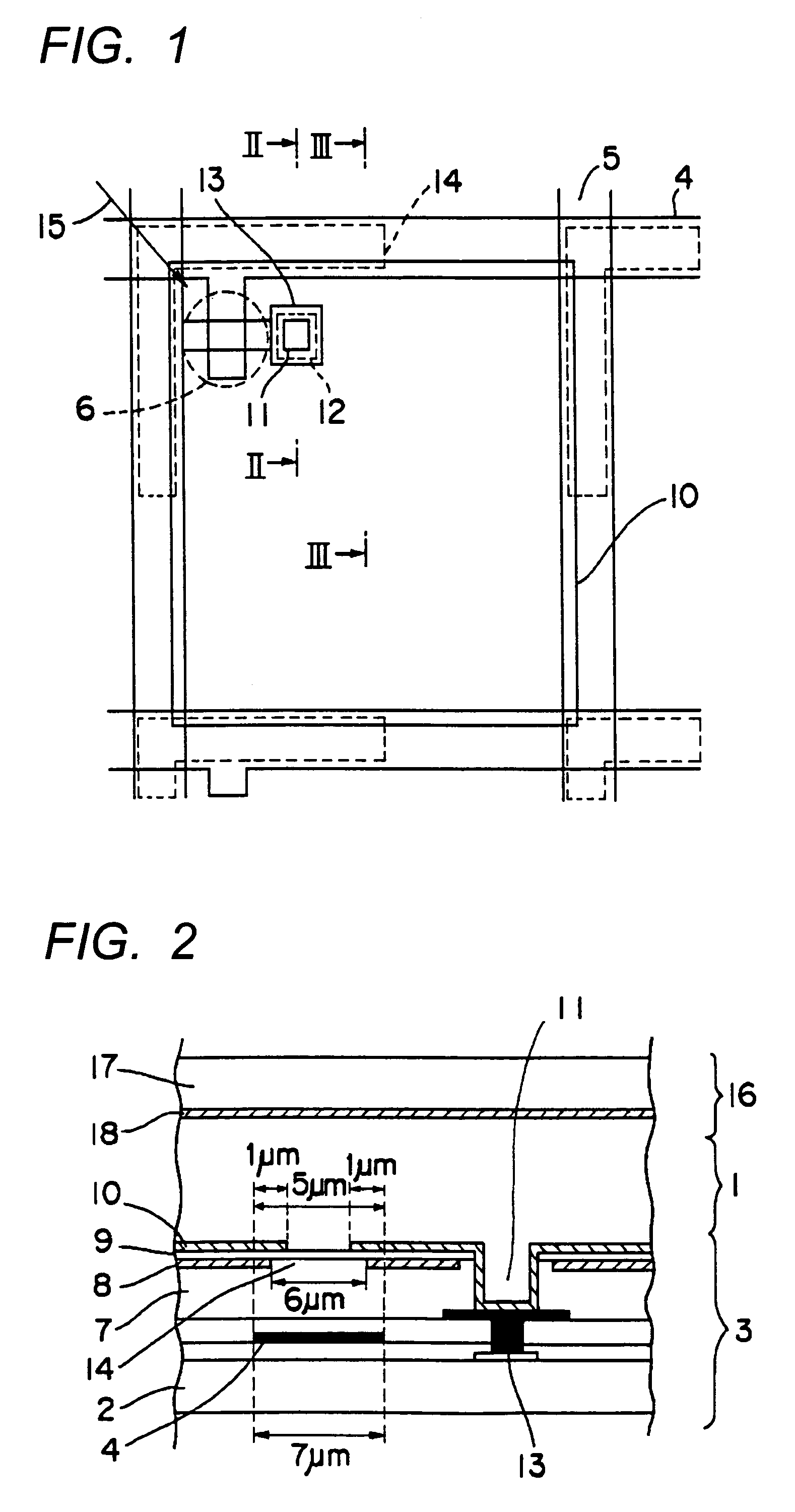
[0059]FIG. 1 is a plan view of a first embodiment of the liquid crystal display apparatus according to the present invention. FIG. 2 is a sectional view taken along line II—II of FIG. 1.

[0060]The liquid crystal display apparatus of the first embodiment has a matrix board 3, an opposed board 16, and a liquid crystal layer 1 sandwiched therebetween. In the matrix board 3, a plurality of parallel scanning lines 4 (only two of which are shown) and a plurality of parallel signal lines 5 (only two of which are shown) are disposed on a glass substrate 2 in such a way that the scanning lines 4 and the signal lines 5 intersect with each other at substantially right angles, and TFTs 6 (only one of which is shown) as switching elements are formed near the intersections of the scanning lines 4 and the signal lines 5. A metal material such as aluminum is used...

second embodiment

(Second Embodiment)

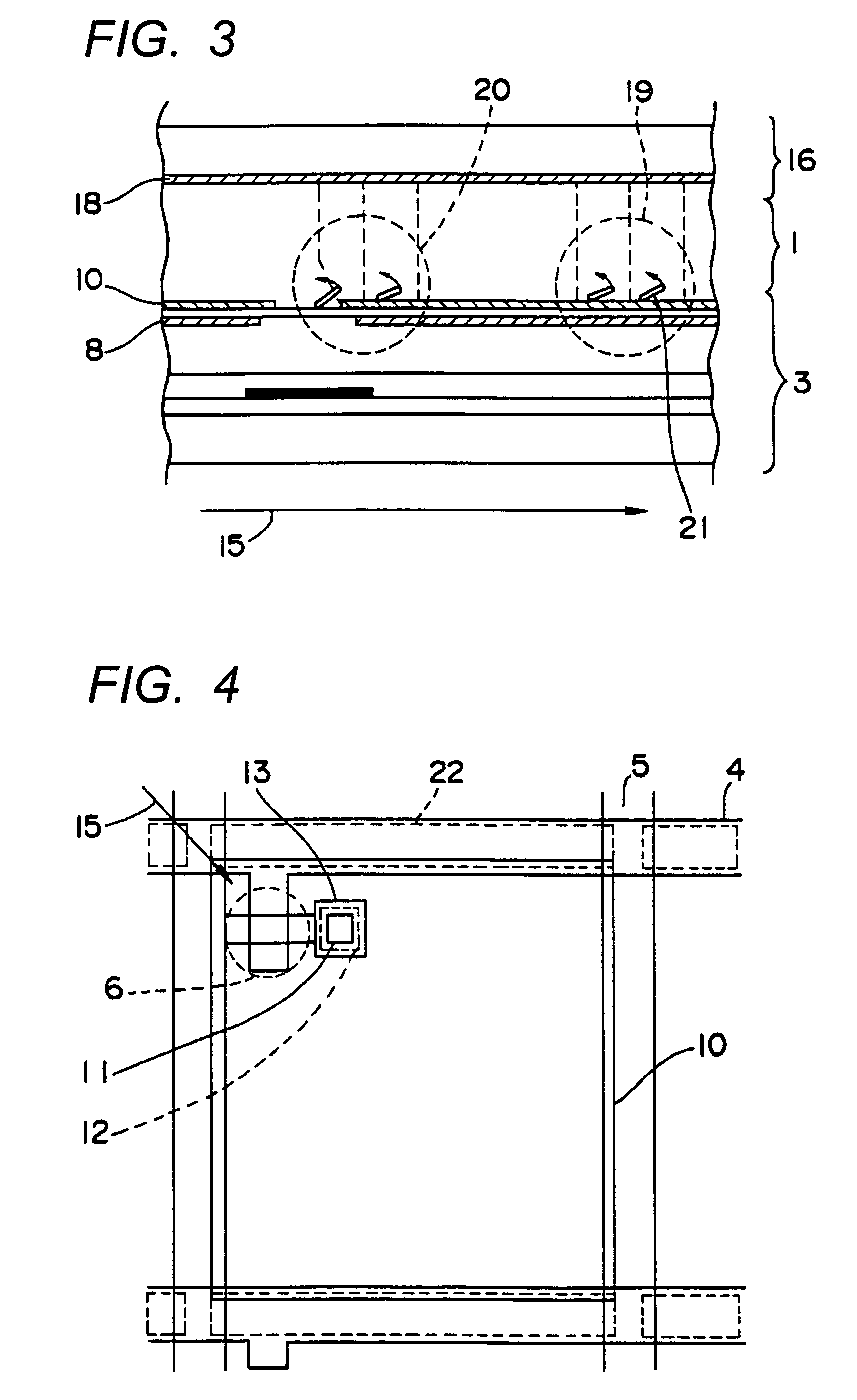
[0071]FIG. 4 is a plan view showing a second embodiment of the liquid crystal display apparatus according to the present invention. The liquid crystal display apparatus of the second embodiment has a sectional view similar to that of the liquid crystal display apparatus of the first embodiment. The liquid crystal display apparatus of the second embodiment is different from the first embodiment in that slits 22 of the auxiliary capacitor electrode are formed along scanning lines 4. Constituent parts of the liquid crystal display apparatus of the second embodiment same as the constituent parts of the first embodiment are denoted by the same reference numerals and the description thereof is omitted herein.

[0072]Because the liquid crystal display apparatus is driven by using alternating current, various driving methods are available with respect to reversing the polarity of a signal voltage. The second embodiment employs a driving method by which the polarity of the s...

third embodiment

(Third Embodiment)

[0075]FIG. 5 is a plan view showing a third embodiment of the liquid crystal display apparatus according to the present invention. FIG. 6 is a sectional view taken along line VI—VI of FIG. 5.

[0076]As shown in FIGS. 5 and 6, the liquid crystal display apparatus of the third embodiment has a matrix board 33 and an opposed board 46 between which a liquid crystal layer 31 is sandwiched. In the matrix board 33, a plurality of parallel scanning lines 34 (only two of which are shown) and a plurality of parallel signal lines 35 (only two of which are shown) are disposed on a glass substrate 32 in such a way that the scanning lines 34 and the signal lines 35 intersect each other at approximately right angles, and TFTs 36 (only one of which is shown) are formed near the intersections of the scanning lines 34 and the signal lines 35.

[0077]A planarization film 37 is formed over the scanning lines 34 and the signal lines 35, formed in the shape of a lattice, and over the TFTs 3...


PUM

PropertyMeasurementUnit
thicknessaaaaaaaaaa
thicknessaaaaaaaaaa
widthaaaaaaaaaa

Abstract

A liquid crystal display apparatus has a plurality of TFTs and pixel electrodes disposed in a matrix form in regions surrounded with scanning lines and signal lines disposed on a glass substrate. The display apparatus also has an auxiliary capacitor electrode formed almost all over a display screen in such a way that the auxiliary capacitor electrode is opposed to the pixel electrodes with interposition of an insulation film therebetween. A slit is formed in the auxiliary capacitor electrode in a region corresponding to a gap between the adjacent pixel electrodes. Each pixel electrode may overlap the scanning lines and / or the signal lines. The width of the slit of the auxiliary capacitor electrode may be larger than the width of the gap between the adjacent pixel electrodes.

Description

BACKGROUND OF THE INVENTION[0001]The present invention relates to a liquid crystal display apparatus of active matrix type.[0002]There is known a liquid crystal display apparatus of a type that has a plurality of pixel electrodes arranged in a matrix form and displays images by controlling voltages to be applied to the pixel electrodes through a plurality of switching elements connected to a plurality of scanning lines and a plurality of signal lines to thereby function as a shutter for adjusting light emitted from a light source such as a backlight. The liquid crystal display apparatus of this type has an advantage that it can display images with higher definition than a display apparatus such as a CRT (cathode ray tube), and is widely used for televisions, computers, information portable or mobile terminals, and the like.[0003]However, as the definition or resolution of images increases, it becomes increasingly difficult to allow the scanning lines, the signal lines, and the auxil...

Claims


Application Information

Patent Timeline
Patent Type & Authority Patents(United States)
IPC IPC(8): G02F1/1335G02F1/13G02F1/1362G02F1/1333G02F1/1343G09F9/30G09F9/35
CPCG02F1/133512G02F1/136213
Inventor NAKAJIMA, MUTSUMI
Owner SHARP KK
Learn More