Insulation layer structure for inductive write heads and method of fabrication

a write head and inductive technology, applied in the direction of metal sheet core heads, instruments, record information storage, etc., can solve the problems of significant difference in thermal mechanical properties between photoresist and magnetic films, poor magnetic properties of sputter deposited on cured photoresist, etc., to improve the properties of magnetic films deposited, the thickness of the write gap can be better controlled, and the effect of less susceptible to cracking

Inactive Publication Date: 2005-10-25
WESTERN DIGITAL TECH INC
View PDF41 Cites 150 Cited by
  • Summary
  • Abstract
  • Description
  • Claims
  • Application Information

AI Technical Summary

Benefits of technology

[0015]An advantage of the present invention is the insulation shell layer is less susceptible to cracking.
[0016]Another advantage of the invention is the insulation shell layer protects the coil during the extensive ion milling process to remove the seed or thicker sputtered high Bs films.
[0017]And another advantage of the invention is that an insulation shell layer greatly improves the magnetic film properties deposited on top, compared to those deposited on photoresist.
[0018]A further advantage of the invention is that the thickness of the write gap can be better controlled when it is on top of insulation, especially when Al2O3 gap material is used.
[0019]These and other objects and advantages of the present invention will become clear to those skilled in the art in view of the description of the best presently known mode of carrying out the invention and the preferred embodiment as described herein and as illustrated in the several figures of the drawings.

Problems solved by technology

Experimental results suggest that magnetic films such as seed layers, which are typically NiFe films with different Fe contents, or other types of high moment magnetic films such as FeXN (X=Al, Ta, Rh, etc), exhibit poor magnetic properties when sputter deposited onto cured photoresist.
This can be attributed to the significant difference in thermal mechanical properties between photoresist and magnetic films, as well as poor grain growth of the magnetic films on photoresist surface.
Also seed removal of the thick sputtered film requires a great amount of over milling into the insulation stack.
Therefore, the integrity of the insulation can be compromised during this process, and the coil may be damaged.

Method used


Image

  • Insulation layer structure for inductive write heads and method of fabrication
  • Insulation layer structure for inductive write heads and method of fabrication
  • Insulation layer structure for inductive write heads and method of fabrication

Examples


Embodiment Construction

[0039]A preferred embodiment of the present invention is a disk drive having an added insulation shell layer. As illustrated in the various drawings herein, a form of this preferred embodiment of the inventive device is depicted by the general reference character 10.

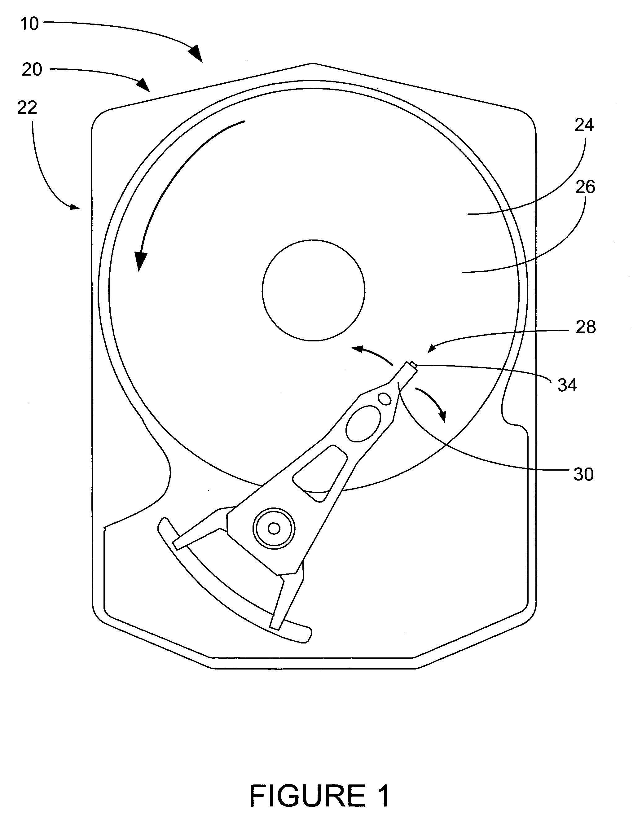
[0040]FIG. 1 shows a simplified top plan view of a magnetic storage device 20, in this case a hard disk drive 22, which generally includes a magnetic storage medium 24, specifically a hard disk 26. A data read / write device 28 is included an arm 30, which supports a slider 34.

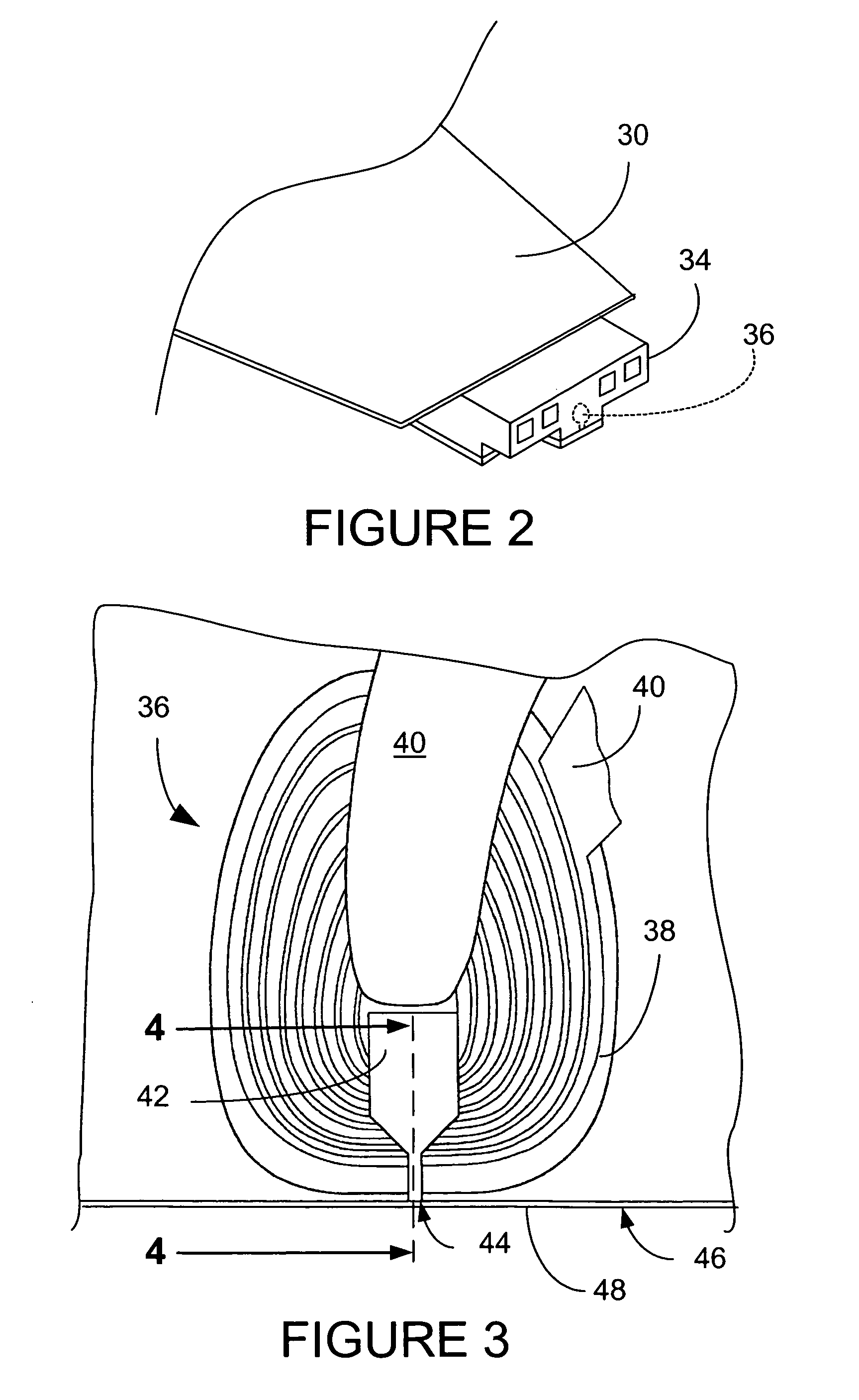
[0041]FIG. 2 illustrates a simplified isometric detail view of the slider 34 into which a magneto-resistive head 36 has been embedded.

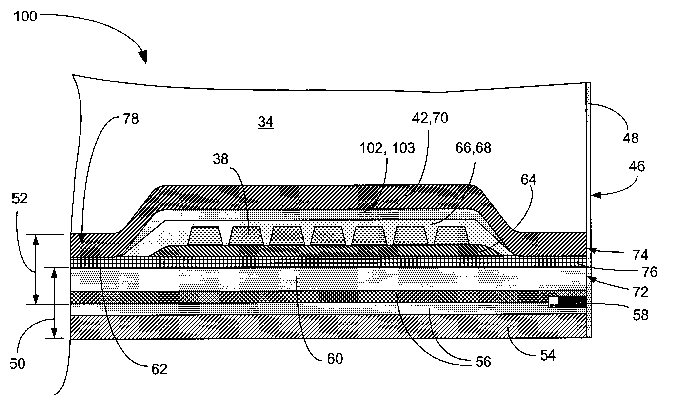
[0042]FIG. 3 shows a top plan view of the components of the magneto-resistive head 36, including a coil 38, leads 40, a top pole piece 42 having a pole tip 44. The surface facing the disk 26 (see FIG. 1) is supported by a layer of air which is established due to the rotation of the disk 26 under the slider 34, and whic...


PUM

PropertyMeasurementUnit
apex angleaaaaaaaaaa
magneticaaaaaaaaaa
moment magneticaaaaaaaaaa

Abstract

A computer disk drive (22) having a write head (52) which includes a coil (38), a photoresist insulation layer (66) formed on the coil (38), and an insulation shell layer (102) which is formed on the photoresist insulation layer (66). In the first preferred embodiment (100), the top pole (42) of the write head (52) is formed on the insulation shell layer (102).
In the second preferred embodiment (200), the disk drive write gap (76) is formed on the insulation shell layer (102) and the top pole (42) of the write head (52) is formed on the write gap (76).
The insulation shell layers (102) in both embodiments are preferably made of dielectric materials (103).
Methods of fabrication for these embodiments are also disclosed.

Description

TECHNICAL FIELD[0001]The present invention relates generally to inductive write heads used in magnetic media storage devices, and more particularly to magneto-resistive disk drive heads.BACKGROUND ART[0002]An inductive write head consists of top and bottom magnetic poles and multi-turn coils to drive the field. The coils are encapsulated in usually one or two insulation layers, which are conventionally made of cured photoresist. A write gap between the top and bottom magnetic poles is typically of dielectric material, and is usually deposited prior to the insulation layer. The seed layer for plating the second writer pole (P2) is deposited using PVD process, such as sputter deposition. By this approach, some portion of the seed layer is on the cured photoresist insulation. The P2 layer is then electroplated into photoresist patterns to form the top pole structure. Experimental results suggest that magnetic films such as seed layers, which are typically NiFe films with different Fe c...

Claims


Application Information

Patent Timeline
Patent Type & Authority Patents(United States)
IPC IPC(8): G11B5/127G11B5/147G11B5/31G11B5/39
CPCG11B5/3106G11B5/3967G11B5/313Y10T29/49032
Inventor CHEN, YINGJIANSIN, KYUSIKBARR, RONALD
Owner WESTERN DIGITAL TECH INC
Why Eureka
Try Eureka