
Articulated sailing watercraft

a watercraft and hull technology, applied in the field of sail-driven watercraft, can solve the problems of affecting the the loss of windward performance, and the general asymmetry of sailing performance of the catamaran when beating or sailing towards the wind, and achieves the effect of increasing the length of the lee hull, convenient use, and being easy to manufactur

Inactive Publication Date: 2005-11-01
BURRELL JAMES S
View PDF7 Cites 14 Cited by
  • Summary
  • Abstract
  • Description
  • Claims
  • Application Information

AI Technical Summary

Benefits of technology

[0010]Yet further objects of the invention are to provide an articulated catamaran structure which is easily fabricated and convenient in use.
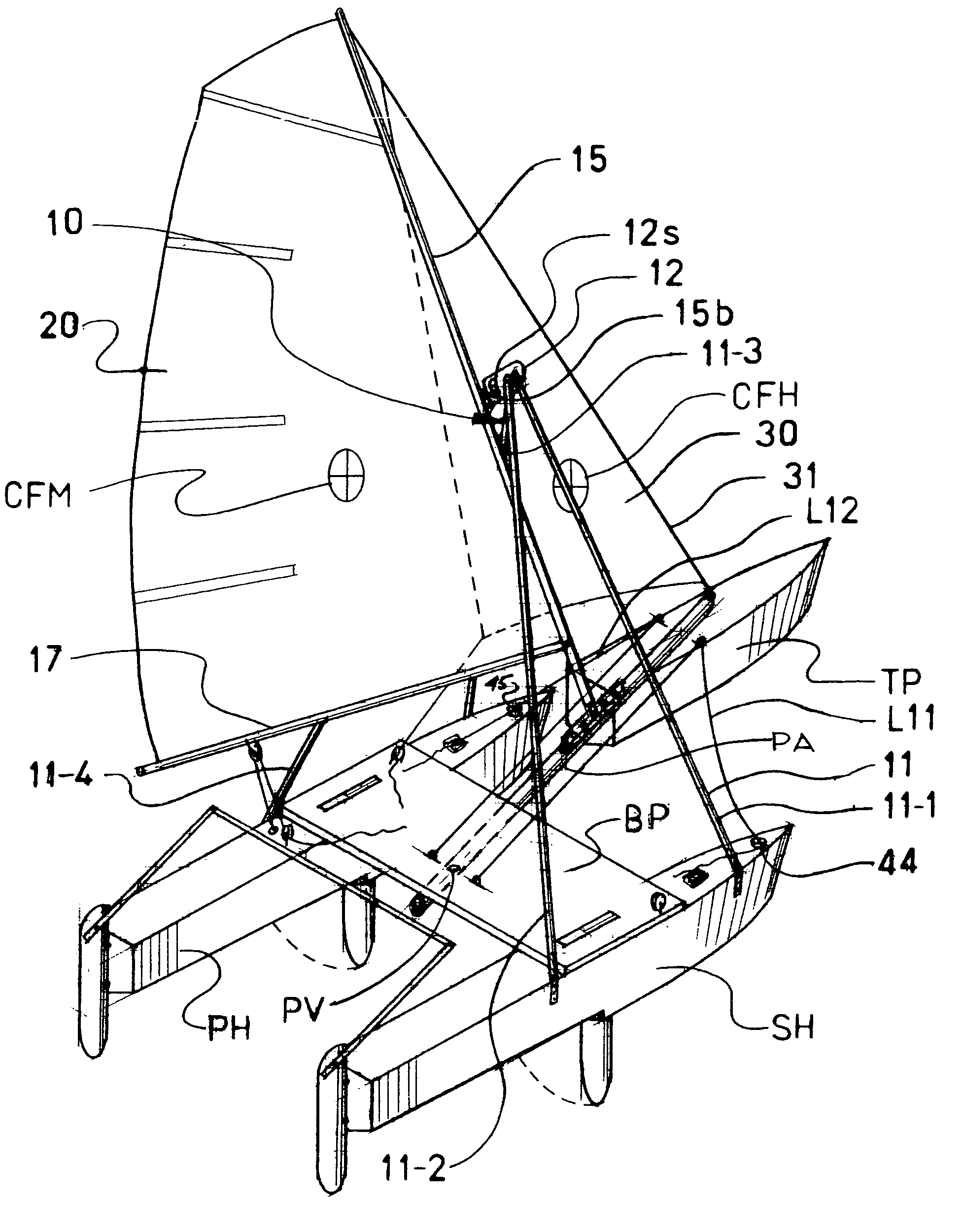
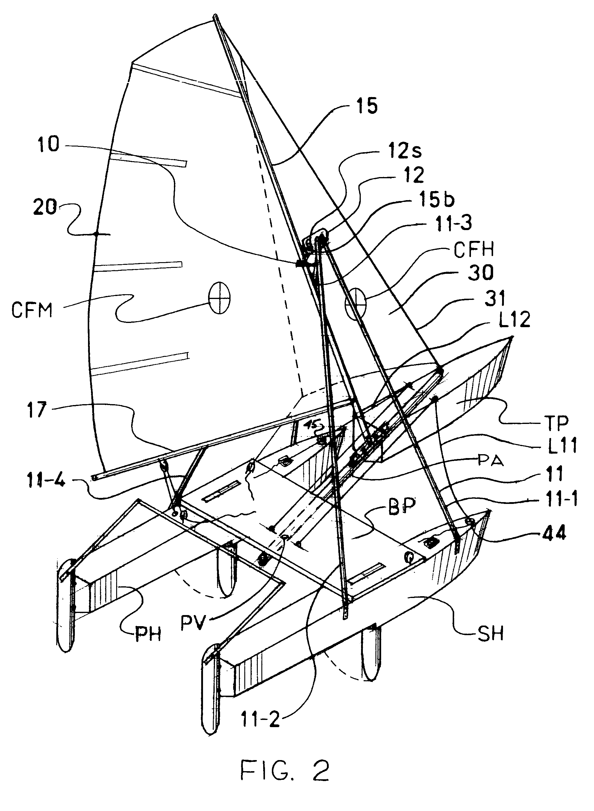
[0011]Briefly, these and other objects are accomplished within the present invention by providing a generally triangular truss mounted across the hulls of the catamaran to suspend from the apex thereof a mast on which a mainsail is deployed. The foot or base of this mast is then selectively connected to one of several mounts on the pivoted arm which, at its end engages the articulated third pontoon. The luff of a headsail is then stretched between the pontoon connection of the arm and a point on the mast above the truss apex, thus forming the fore triangle, or forestay, with two pairs of rigid shroud pieces adjustably connected to the hulls to form the truss apex. In this manner the craft is generally conformed as a sloop rigged sailing catamaran in which the third pontoon is carried by the headsail to align ahead of the lee hull, moving the geometry of the sail rigging towards a vertical position. Along with this benefit the further convenience of tacking is achieved in a sail rig that essentially duplicates sloop rigging. Thus the widely familiar sail handling features of a sloop rig are effectively combined with a novel coordination of the sails and an articulated hull platform.
[0012]Those skilled in the art will appreciate that the foregoing configuration effectively combines the hull speed benefits of the pontoon increased length of the lee hull with a concurrent angulation of the sail rigging towards the vertical right above this hull. This increased sail effectiveness can then be further optimized by conforming each of the fixed hulls as a stepped hull with the upper hull surface opened both to trap the relative wind and to permit manipulation of pivoted fins or dagger boards extending through a lower opening that also serves to ventilate the step. The rear portions of each of the hulls are thus ventilated, reducing the surface drag thereof and thereby further improving vessel performance. In this manner all the advantages of the articulated vessel geometry are fully optimized with minimal added complexity for the user.
[0013]In this manner the added length of the lee hull increases its buoyancy, promoting planing, while also shifting the effective center of gravity along with the lateral motion thereof. As result, the lightened windward hull is more responsive to the body motions of the user effecting the necessary sail controls through the well familiar control provisions of a sloop rig. While in accordance with the prior art teachings the directional alignment of the third hull is controlled by a trapezoidal cable rig extending from the cross bridging along the pivoted arm to corresponding connections on the third pontoon, this directional rigging may be further augmented by a set of trim control lines extending over pulleys on each of the hulls again to the rearward control position of the user on the windward hull. These trim features, adjustments in mast rake geometry and the sail control lines of a sloop rig provide for full adjustment for optimum sailing performance.
[0014]More importantly, the stiff, but light weight, truss configuration bridging across the catamaran hulls synergistically combines with the effective light hull loading to promote planing which can then be finther optimized by a stepped hull surface that is even further optimized by a ventilation arrangement of the rear surface portions thereof. The windward cant of the masthead that results from this rigging geometry also obtains a net lifting component at low heel angles, thus further reducing the effective weight of the craft and the resulting immersed surface of the hull, decreasing drag. Thus the interesting features of the prior art teaching referred to above are inventively modified to result in a practical, efficient and inexpensive watercraft.

Problems solved by technology

The asymmetric aspects of a single stabilizing outrigger, however, result in grossly asymmetrical sailing performance across and into the wind and the symmetry of a catamaran hull platform is therefore most often associated with the early development of sail surfaces in the Pacific.
This beneficial symmetry of a catamaran, however, has its own disadvantages, namely the characteristically low performance of a catamaran when beating or sailing towards the wind.
This loss of windward performance, which has become more pronounced as sail efficiency improved, stems from the inherent offset of the sail surfaces from the center of buoyancy, an offset that imposes a turning moment about the volumetric center of the lee hull.
It is, of course, the combination of a symmetrical deployment of the sail rigging relative an asymmetrical buoyancy point that produces this moment, and the wider the catamaran platform the less efficient it is to the wind.
While the foregoing new development in catamaran architecture represents a significant advance in the art, its general acceptance has not followed, primarily because of the inherent difficulties in sail handling associated with the articulated sail tack where even the developer, himself, resorts to gybing as the primary method for changing tacks.
In addition the above developer, while recognizing the benefits of a stepped hull, fails to optimize same.

Method used


Image

  • Articulated sailing watercraft
  • Articulated sailing watercraft
  • Articulated sailing watercraft

Examples


Embodiment Construction

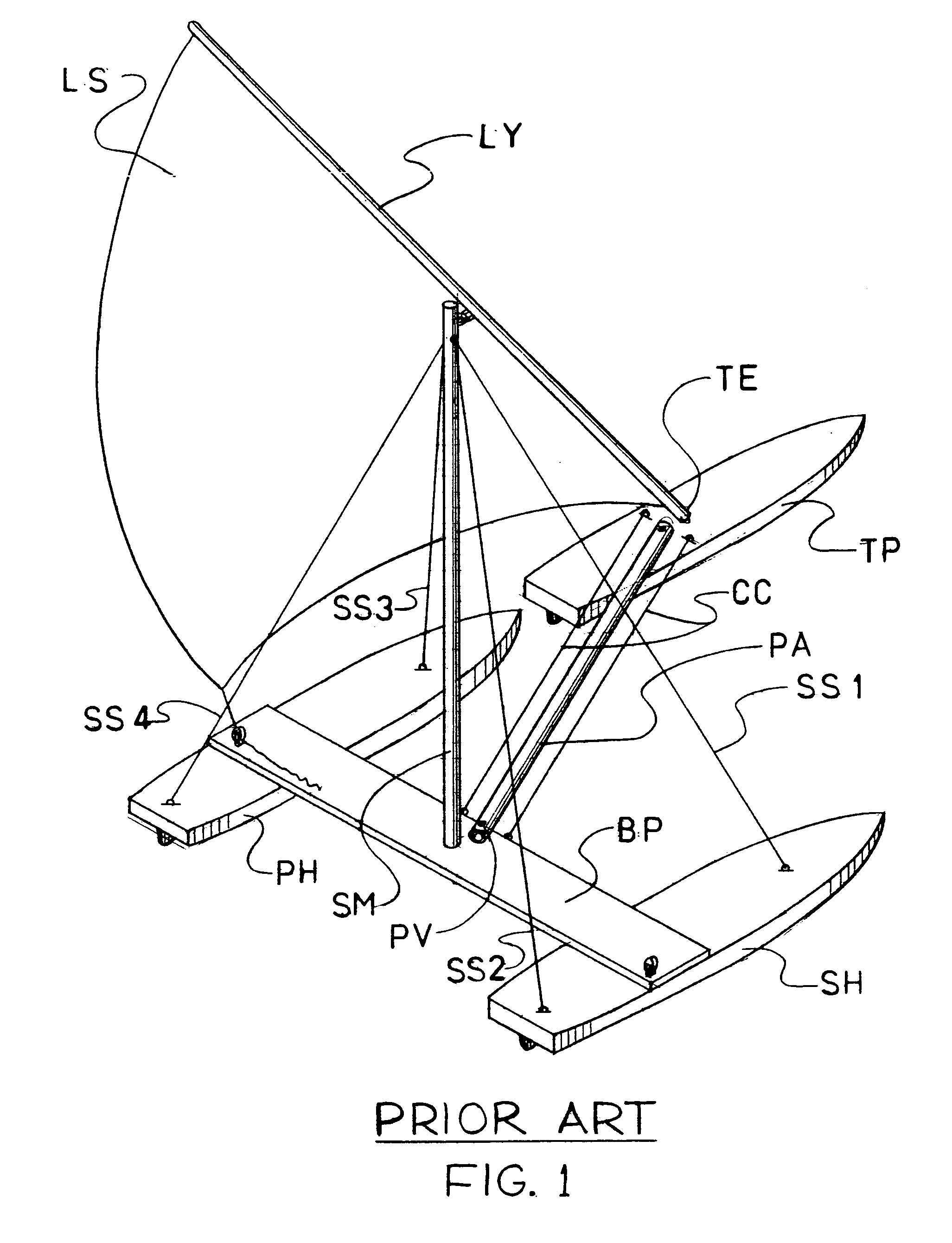
[0022]The prior art development of a sailing catamaran provided with a pivotally articulated third pontoon is best described by reference to FIG. 1 wherein the starboard and port hulls SH and PH, respectively, are fixed in spaced parallel alignment by a bridging piece BP which, at its center, supports a stub mast SM. A set of shrouds SS1–SS4 extending in pairs from the respective hulls are then utilized to rig the stub mast vertically to support the long yard LY (otherwise sometimes referred to as the crossbar) of what is most closely described as a lateen rigged sail LS. While in current practice sail LS may be fully battened and shaped for maximized performance, this particular rigging demands that, like in a windsurfer, directional changes are best effected by gybing. In the particular prior art example referred to herein the use of a lateen rig is dictated by a pivoted arm PA extending forwardly from a pivot PV centered on the bridging piece BP to articulate a third pontoon TP i...


PUM


Abstract

In a sailing catamaran provided with a forwardly directed pivoted arm carrying at the free end a third pontoon into alignment in front of either of the catamaran hulls a triangular truss assembly is provided bridging across the hulls. The apex of the truss assembly is then engaged to a point along the length of a mast which has its foot or base resting on the arm. A forestay stretched between the mast and the end of the arm supports a headsail while a mainsail is mounted on the mast.

Description

BACKGROUND OF THE INVENTION[0001]1. Field of the Invention[0002]The present invention relates to sail driven watercraft, and more particularly to a sailing catamaran with its sails supported in a bridging trapeze to articulate along with an articulated third pontoon laterally displaced to align in front of the lee hull when tacking.[0003]2. Description of the Prior Art[0004]The inherent benefits of a sailing catamaran are universally well known and have been appreciated throughout, and even before, recorded history. Specifically, the wide spacing between the hulls of a catamaran allows for a very narrow hull shape with the consequent reduction in drag. Even earlier the low drag aspects of a long and narrow hull, stabilized by an outrigger, have been universally appreciated and there is some suggestion that it is this appreciation that has promoted human migration across the various Pacific islands. The asymmetric aspects of a single stabilizing outrigger, however, result in grossly ...

Claims


Application Information

Patent Timeline
Patent Type & Authority Patents(United States)
IPC IPC(8): B63B35/00B63B1/12B63H9/06
CPCB63B1/125B63H9/06B63H9/0685B63B2001/145B63B2015/0033B63B1/14
Inventor BURRELL, JAMES S.
Owner BURRELL JAMES S
Learn More