Device for securing a door leaf against unintentional deflection

a technology for securing doors and windows, applied in carpet fasteners, dwelling equipment, applications, etc., can solve the problems of preventing the door from being moved at all, difficult to support doors of this type, and requiring a large amount of effort to construct a device of this type, so as to prolong the service life and improve the operation reliability of these devices.

Inactive Publication Date: 2005-11-01
DORMA GMBH & CO KG
View PDF25 Cites 14 Cited by
  • Summary
  • Abstract
  • Description
  • Claims
  • Application Information

AI Technical Summary

Benefits of technology

[0020]The invention is based on the task of simplifying the known devices for preventing the leaves of a door system from being swung out of position

Problems solved by technology

It is difficult to support doors of this type in such a way that they can be intentionally released and swung out of position because, first, the leaves of a revolving door must be held securely in their normal position, in which they can form an “X” in cross section, for example, when the door is revolving.
Because the positions of the door leaves are usually scanned for control purposes, situations in which the leaves have been unintentionally swung out of their normal positions can cause problems with the normal operation of the door and prevent the door from being moved at all.
The effort required to construct a device of this type is considerable; it is complicated to install; and it is difficult to adjust the elastic forces

Method used


Image

  • Device for securing a door leaf against unintentional deflection
  • Device for securing a door leaf against unintentional deflection
  • Device for securing a door leaf against unintentional deflection

Examples


Embodiment Construction

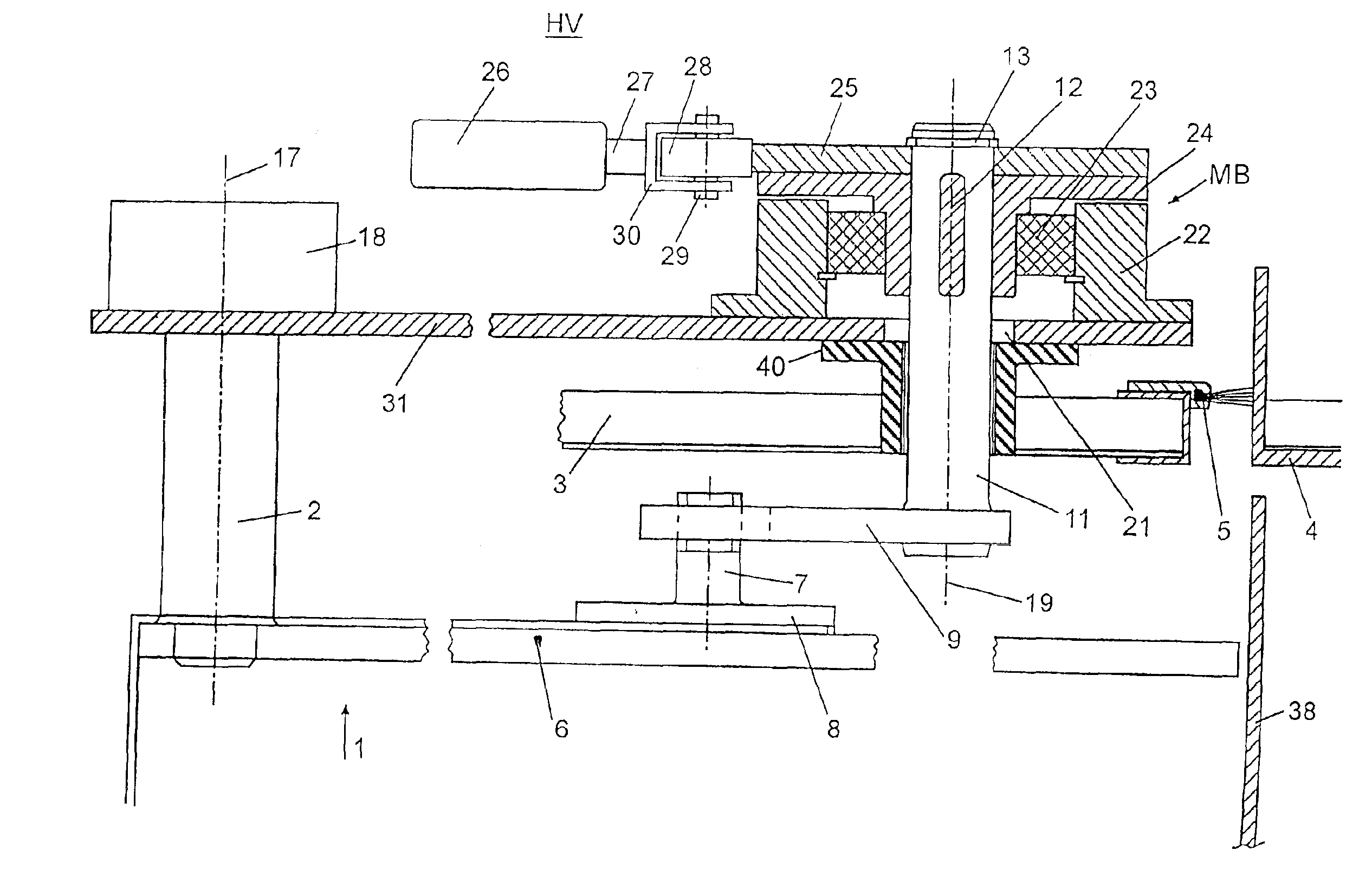
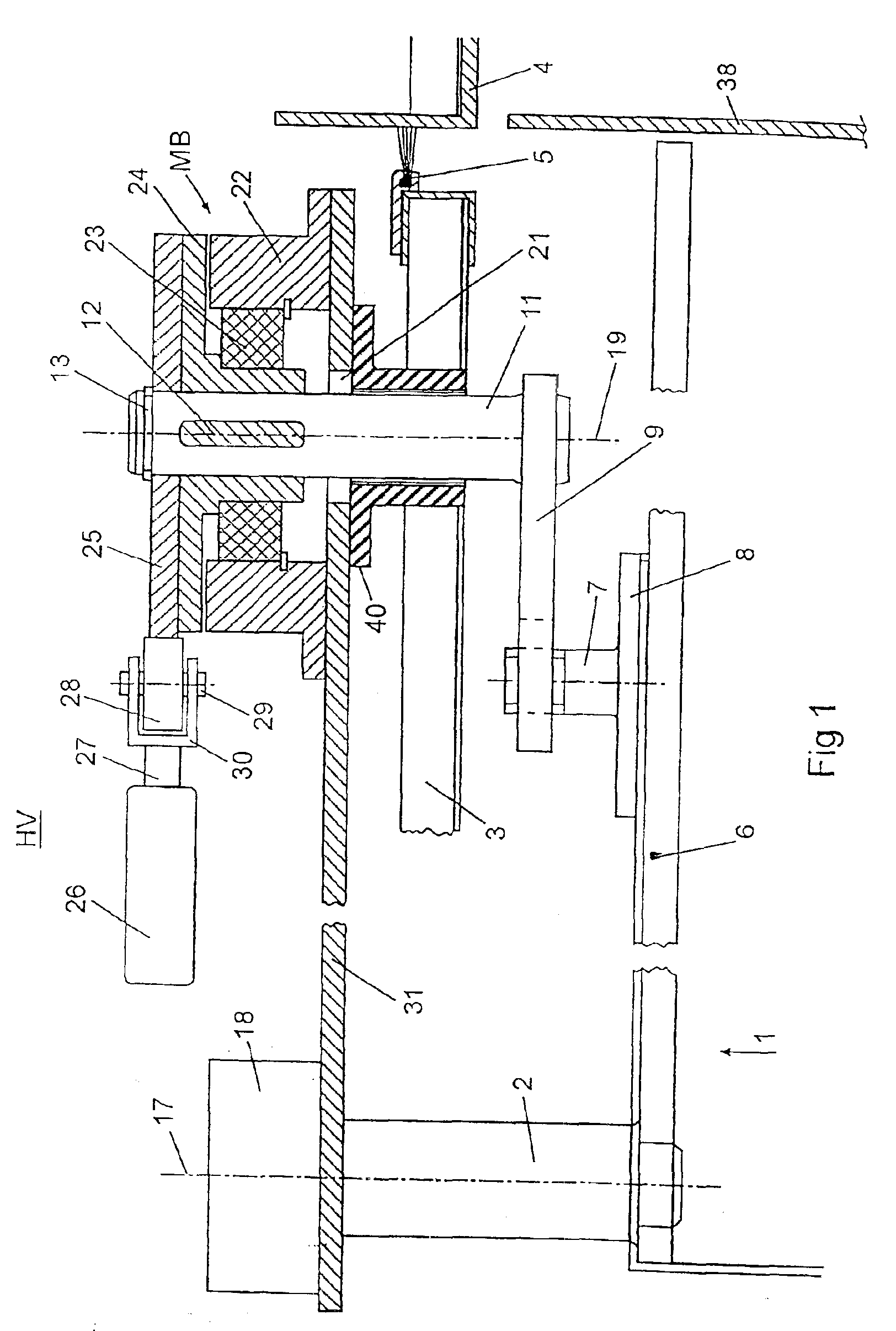
[0032]A retaining device, designated “HV” overall in FIG. 1, is provided for each leaf 1 of a multi-leaf revolving door, shown in FIG. 4, which door is installed within the boundary walls 38, the retaining device being located opposite the upper area of the frame 6 of the leaf. Each leaf 1 is supported in such a way by part of a leaf hanger 2, which forms part of a leaf support 18, that the leaf can pivot around an axis 17. The leaf supports 18 are attached to the roof structure 31, which revolves along with the door and which is concealed by a ceiling 3, which extends between the boundary walls 4, which form a cylindrical jacket.

[0033]A brush type seal 5 is provided all the way around between the ceiling 3 and the boundary walls 4.

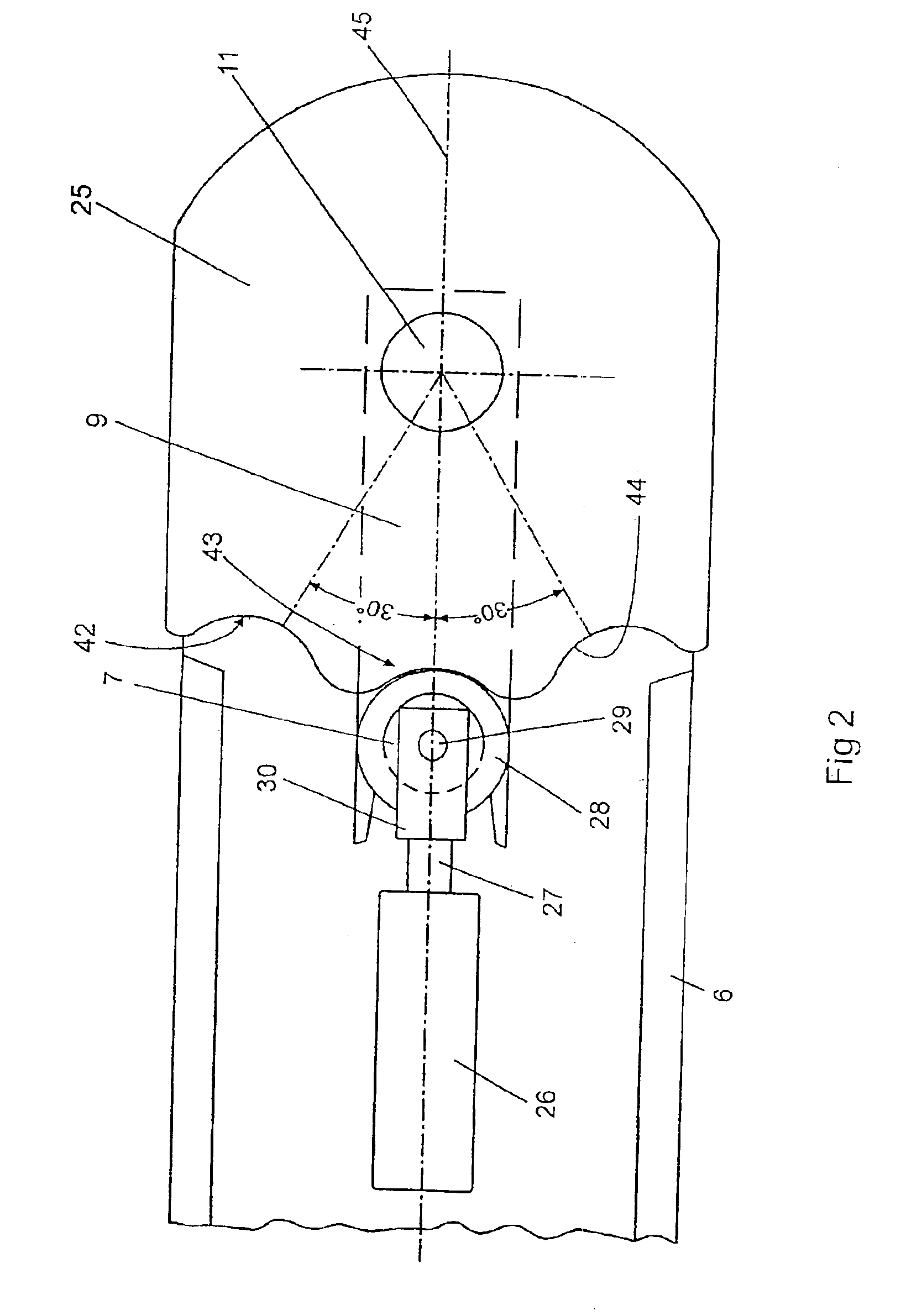
[0034]Each leaf 1 has its own retaining bolt 7, which is permanently connected by a flange 8 to the upper edge of the leaf frame 6. As FIG. 3 in particular shows, a fork arm 9 works together with each retaining bolt 7. This arm is rotatably attached to on...


PUM


Abstract

A driven part can be pivotably mounted to the door frame so that, in a starting position, it engages a driving part fixed to the leaf frame in order to fix the position of the door leaf with respect to the door frame. An electromagnetic brake generates a moment to retain the driven part in the starting position when electrical current is supplied, and allows the driven part to pivot from the starting position when electrical current is not supplied. The driven part is held in the starting position when the driven part returns to the starting position and no moment is generated by the electromagnetic brake.

Description

PRIORITY CLAIM[0001]This is a U.S. national stage of application No. PCT / EP01 / 01417, filed on Feb. 9, 2001. Priority is claimed on that application.BACKGROUND OF THE INVENTION[0002]1. Field of the Invention[0003]The invention pertains to a device for preventing the door leaves of a door system with at least one leaf used in an escape and rescue route from being swung unintentionally out of position.[0004]2. Description of the Related Art[0005]It is known that revolving doors, for example, have leaves which rotate around a central axis. The leaves extend between the central, pillar-like drive component and the boundary walls of the revolving door, which are designed in the form of segments of a cylinder. The leaves are supported on the central drive component in such a way that they can pivot, so that, after the revolving door has been stopped, a retaining force can be overcome and the leaves swung out of their normal, radially oriented operating position, in which they are perpendic...

Claims


Application Information

Patent Timeline
IPC IPC(8): E05D15/00E05D15/02E06B3/90F16D65/14E05B65/00E05F15/00F16P1/04
CPCE05D15/02E06B3/90E05B65/0071E05Y2900/132F16D2121/20Y10S292/65Y10T292/0909Y10T292/11Y10T292/1021Y10T292/1082Y10T292/0908
Inventor ROCKENBACH, MANFRED
Owner DORMA GMBH & CO KG
Why Eureka
Try Eureka