Surface roughening treatment method of object being treated, and apparatus therefor

a surface roughening treatment and object technology, applied in the direction of lapping machines, instruments, manufacturing tools, etc., can solve the problems of large-scale equipment, derusting of such methods, and reducing efficiency in rotational utilization, so as to achieve high quality of goods

Inactive Publication Date: 2005-11-01
AOKI MOTOHISA
View PDF6 Cites 3 Cited by
  • Summary
  • Abstract
  • Description
  • Claims
  • Application Information

AI Technical Summary

Benefits of technology

[0007]The invention has been thought of in view of the above situation, and provides means capable of stably mass-producing an article, which is inexpensive and high in quality of goods and surfaces of which are roughened, in particular, a substrate for electrophotographic photosensitive body.

Problems solved by technology

However, there is a need of supplying a medium, separating a medium made fine due to collision, replenishing a medium, or the like, which requires a large-scaled equipment.
However, only effects of not much more than descaling, derusting can be expected of such methods.
Therefore, the method appears at a glance to be valuable as a matte treatment method for surfaces of an object being treated, but it exceedingly detracts efficiency in terms of utilization of a rotational magnetic field and exceedingly degrades a commercial value because no account is taken of that blackening phenomenon of surfaces of an object being treated, caused due to the fact that fine powder of an object being treated is generated as the surface roughening treatment proceeds and the fine powder remains in the vessel as it is.
Further stated, no account is taken to obtain uniformity of quality in the case of industrial application.
Also, when applied repeatedly to the electromagnetic type surface roughening method in an ordinary manner, magnetic abrasive grains are gradually increased in residual magnetic forces, which impede vibratory move at random to make it difficult to obtain a desired surface roughness.
Cost for finishing cutting accounts for a major part of cost for treatment, and so a demand for cost reduction is pressing.

Method used


Image

  • Surface roughening treatment method of object being treated, and apparatus therefor
  • Surface roughening treatment method of object being treated, and apparatus therefor
  • Surface roughening treatment method of object being treated, and apparatus therefor

Examples


example 1

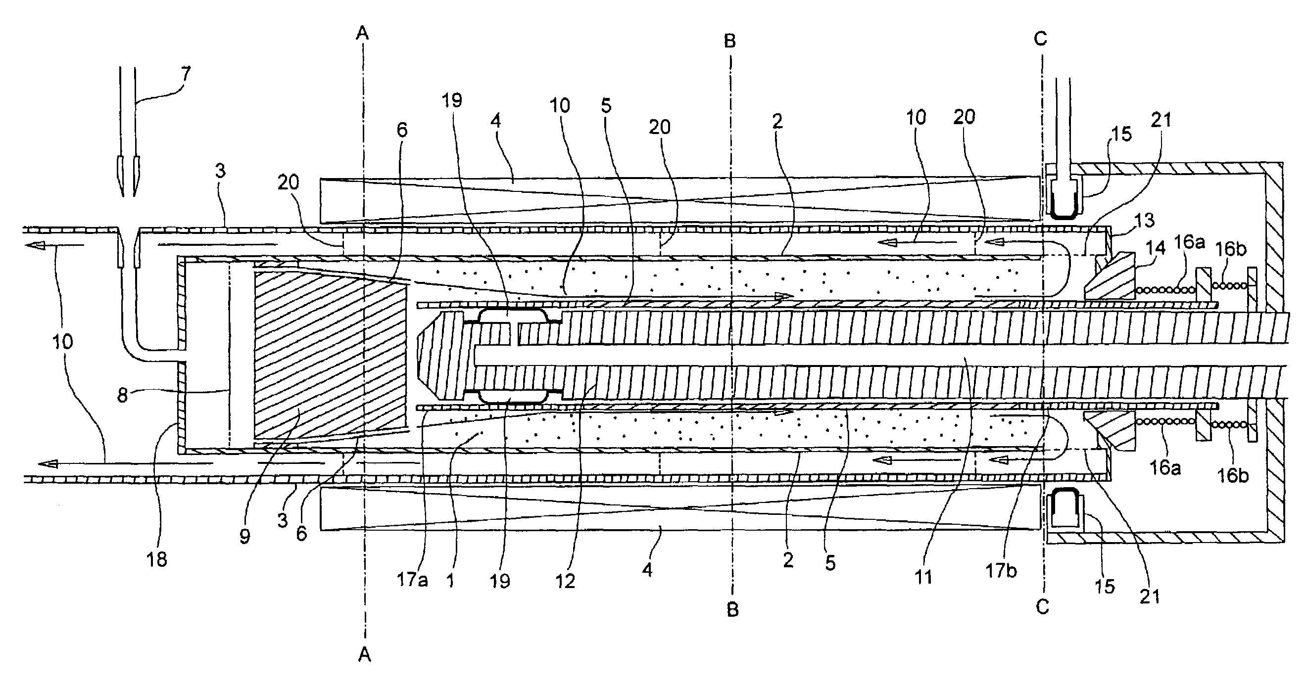
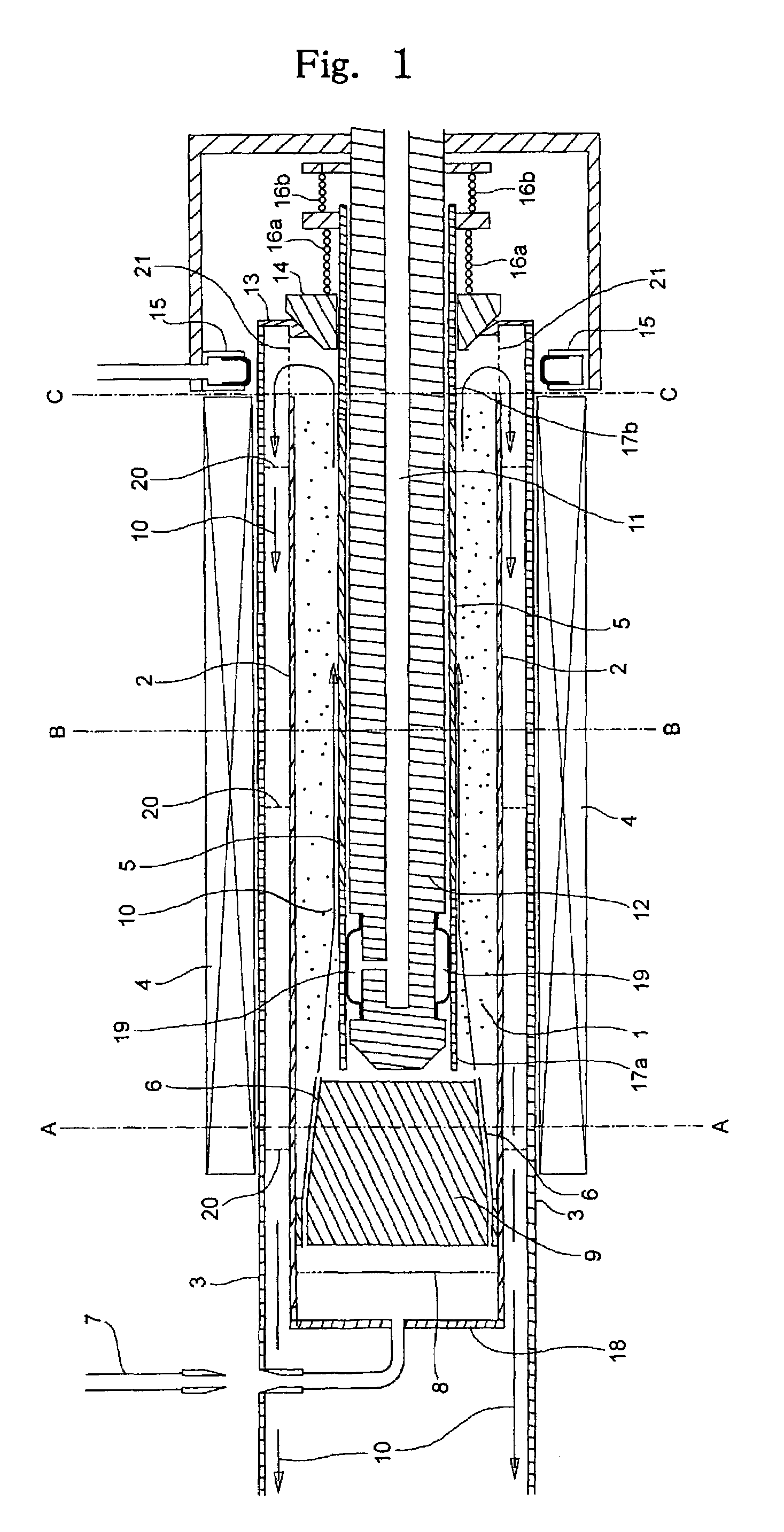
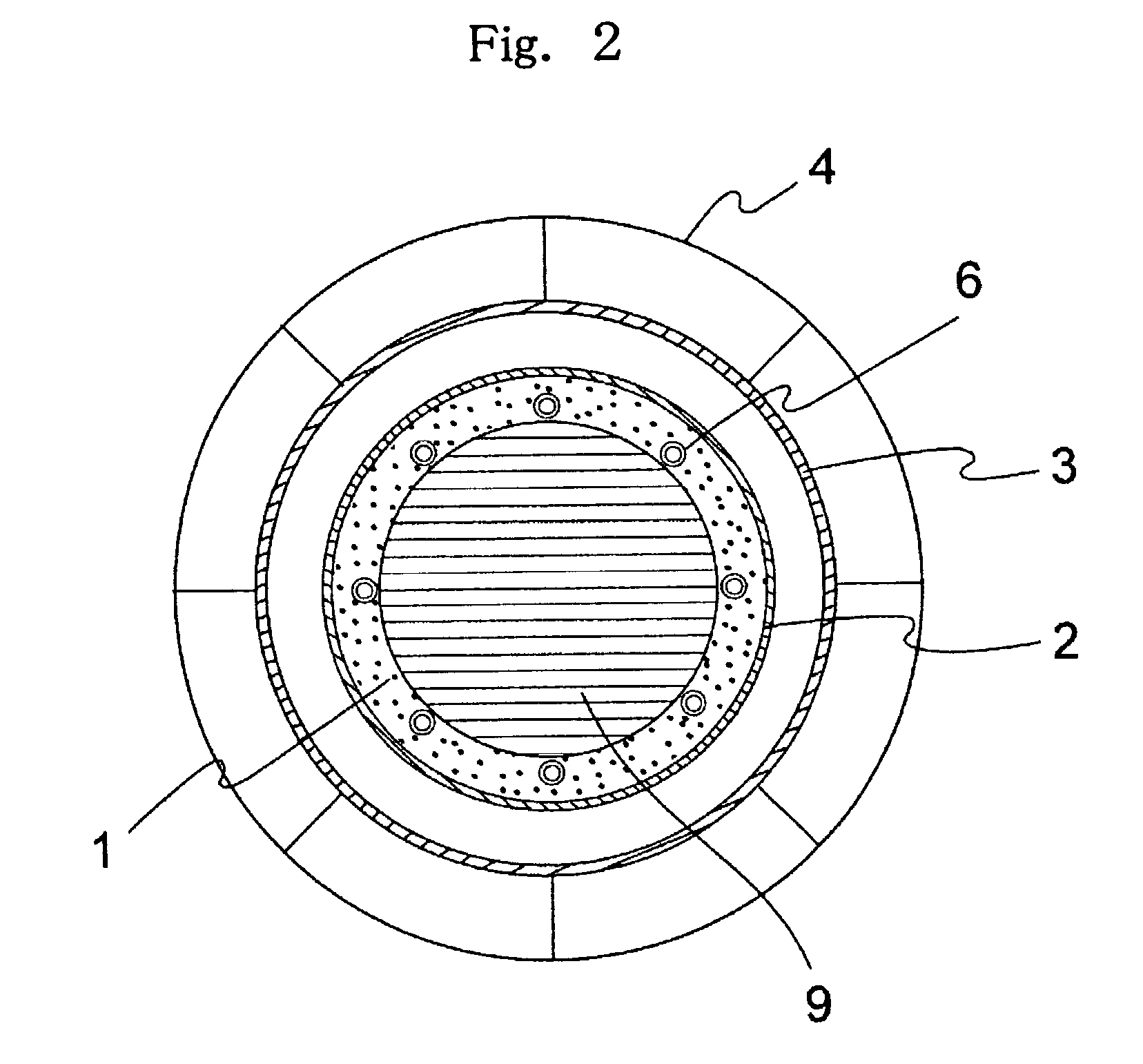
[0018]An apparatus shown in FIG. 1, that is, an apparatus having the following constituent members, was used. In addition, FIGS. 2 to 4 are a cross sectional view taken along the line A—A in FIG. 1, a cross sectional view taken along the line B—B, and a cross sectional view taken along the line C—C (for the sake of avoiding complexity in the figures, a rotational magnetic field generating device 4 described later is indicated by lines. Also, abrasive grains as a surface roughening medium are symbolically shown in the figures as well as FIG. 1). Here, in descriptions regarding directions in the specification as well as in claims, “right” indicates a sense toward the line C—C from the line A—A in FIG. 1 while “left” indicates a sense toward the line A—A from the line C—C in FIG. 1.

(1) Rotational Magnetic Field Generating Device 4:

[0019]The device is composed of two-pole stator (inner diameter: 83 mmΦ, length of coil winding: 475 mm) (the stator is electrically connected to a three-pha...

example 2

[0039]Surface roughening treatment on objects 5 being treated (the number of objects being 20) was performed in the same apparatus and operating condition as those in the example 1 except that no introduction of compressed air into a surface roughening treatment vessel 2 was made and that “demagnetizing operation” and “abrasive grain uniformizing operation in an axial direction” were not performed. Like the example 1, a first object being treated involved less adherence of fine powder resulted from the object being treated, and had white surfaces. Also, no difference in dent density in a longitudinal direction was found on the object 5 being treated (a state shown in FIG. 6(d)). However, it was recognized that a second object being treated involved somewhat adherence of fine powder resulted from the object being treated, surfaces of a third object being treated began to become black, the more the number of objects being treated, the more adherence of fine powder resulted from an obj...

example 3

[0041]Surface roughening treatment on objects 5 being treated (the number of objects being 20) was performed in the same apparatus and operating condition as those in the example 2 except that after surface roughening treatment of one object 5 being treated was terminated, only a work and the iron core 12 were taken out from the rotational magnetic field generating device 4, and after a cover or the like (whatever will do provided that the central hole of the seal member 13 was plugged) plugged, introduction of compressed air and application of voltage were simultaneously performed for 30 seconds, introduction of compressed air was stopped and only application of voltage was performed for 5 seconds, and then a new work was charged. Like a first object being treated, second and succeeding objects being treated involved less adherence of fine powder resulted from the objects being treated, and the objects 5 being treated kept white surfaces. Of course, no difference in dent density in...


PUM

PropertyMeasurementUnit
lengthaaaaaaaaaa
inner diameteraaaaaaaaaa
lengthaaaaaaaaaa

Abstract

Disclosed are a method of causing abrasive grains to collide against and contact with an object being treated to form surfaces of the object being treated into a matte, specifically, a rotational magnetic field is applied on magnetic abrasive grains to cause the same to vibratingly move at random to collide against and contact with an object being treated to obtain a matte.

Description

BACKGROUND OF THE INVENTION[0001]The present invention relates to a method of causing abrasive grains to collide against and contact with an object being treated to form surfaces of the object into a matte. Specifically, a rotational magnetic field is applied on magnetic abrasive grains to cause the same to vibratingly move at random to collide against and contact with an object being treated to obtain a matte. More specifically, the invention is applied on finishing of an aluminum pipe for electrophotographic photosensitive body.[0002]Conventionally, the dry shot blasting method and the wet shot blasting method have been used for matte treatment of an object being treated. These methods cause jet of a working fluid, for example, compressed air, or acceleration of a medium with the use of an impeller to cause the same to collide against an object being treated to finish surfaces of the object being treated. However, there is a need of supplying a medium, separating a medium made fin...

Claims


Application Information

Patent Timeline
Patent Type & Authority Patents(United States)
IPC IPC(8): B24B31/00B24B31/10G03G5/00B24B31/112B24B37/00G03G5/10
CPCB24B31/102
Inventor AOKI, MOTOHISA
Owner AOKI MOTOHISA
Why Eureka
Try Eureka