
Endovascular aneurysm repair system

a technology for aneurysms and endovascular aneurysms, which is applied in the direction of prosthesis, surgical staples, blood vessels, etc., can solve the problems of aneurysm formation, aneurysm dilatation, and aneurysm growth, so as to achieve less trauma, less traumatic, and less invasive

Inactive Publication Date: 2005-11-01
MEDTRONIC VASCULAR INC
View PDF77 Cites 385 Cited by
  • Summary
  • Abstract
  • Description
  • Claims
  • Application Information

AI Technical Summary

Benefits of technology

The present invention provides improved methods and systems for implanting vascular stents and stent-grafts into blood vessels, particularly for reinforcing aneurysms, particularly abdominal aortic aneurysms. The methods involve expanding a scaffold of the prosthesis at the implantation site and then introducing fasteners to secure the scaffold in place. The scaffold can be expanded using a balloon or other expanding mechanism, and the fasteners can be introduced through the fabric or the scaffold structure. The fasteners can be helical or other types of fasteners, and they are introduced in a spaced-apart pattern to secure the graft firmly in place. The invention provides improved methods and systems for implanting vascular stents and stent-grafts, which can better reinforce damaged blood vessels and prevent aneurysms.

Problems solved by technology

The weakening of a vessel wall from damaged or diseased can lead to vessel dilatation and the formation of an aneurysm.
Left untreated, an aneurysm can grow in size and will eventually rupture.
The rupture of an aortic aneurysm results in massive hemorrhaging and has a high rate of mortality.
The prosthetic grafts for these procedures are usually unsupported woven tubes and are typically made from polyester, ePTFE or other suitable materials.
However, these procedures require a large surgical incision and have a high rate of morbidity and mortality.
In addition, many patients are unsuitable for this type of major surgery due to other co morbidities.
These graft attachment means do not provide the same level of attachment when compared to suture and can damage the native vessel upon deployment.

Method used


Image

  • Endovascular aneurysm repair system
  • Endovascular aneurysm repair system
  • Endovascular aneurysm repair system

Examples


Embodiment Construction

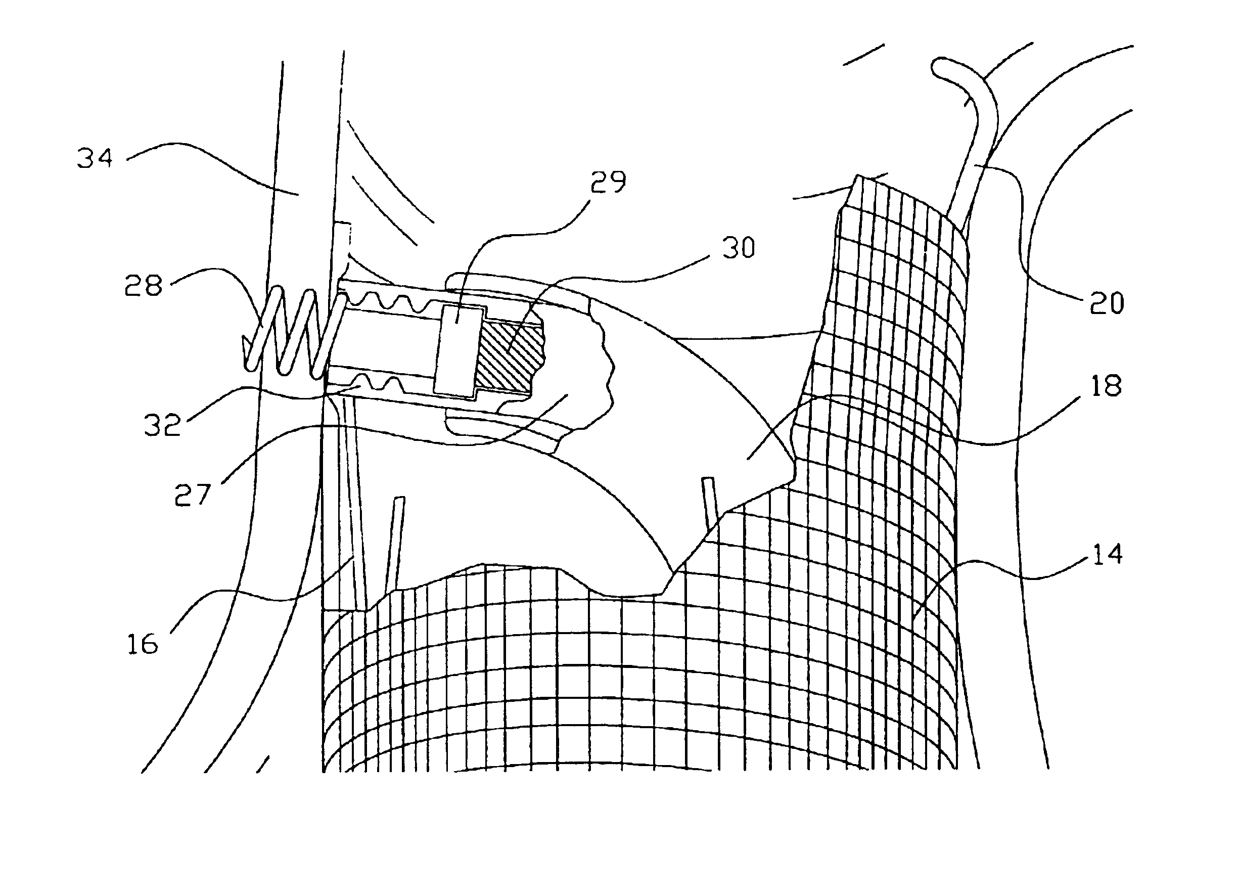
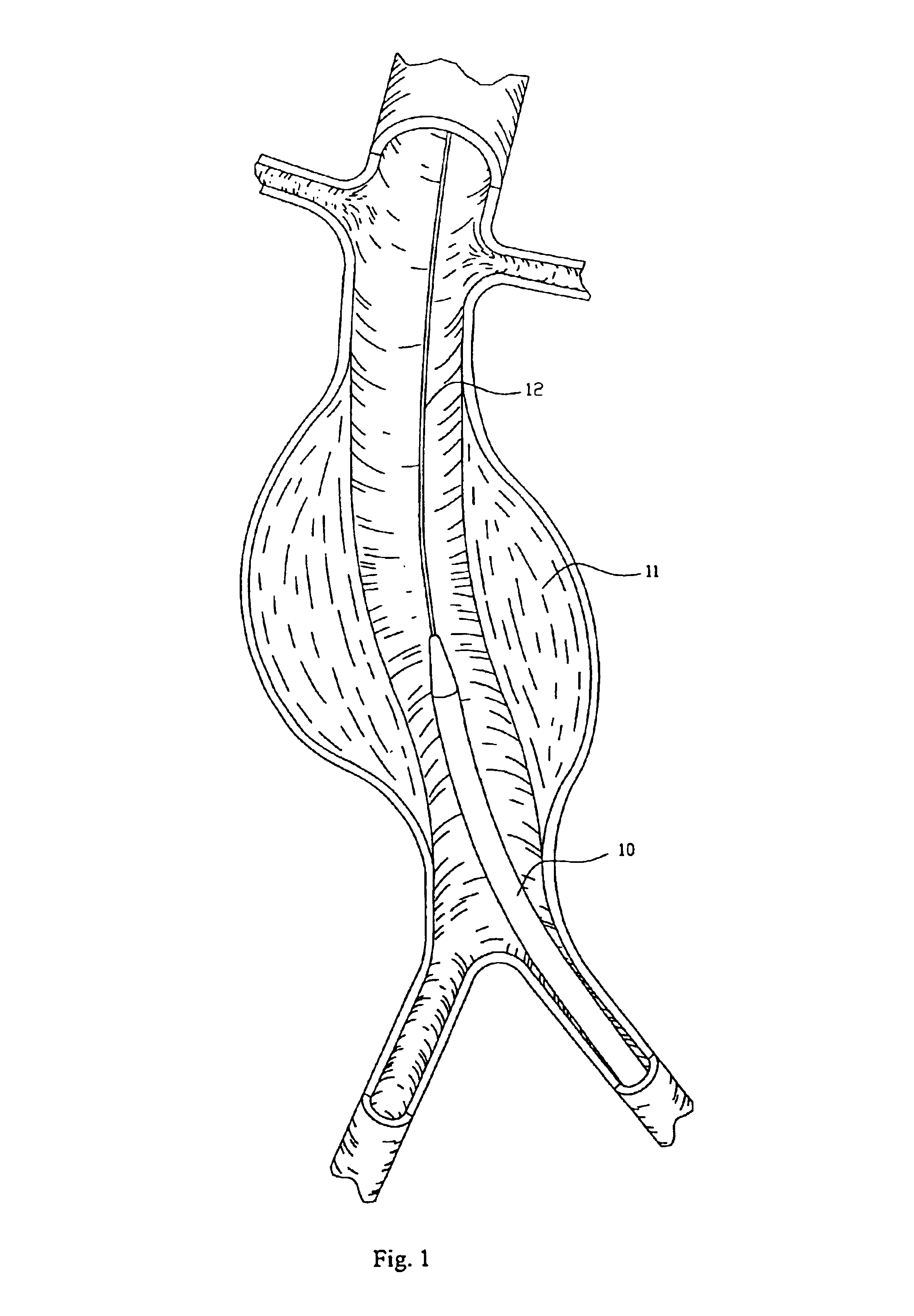
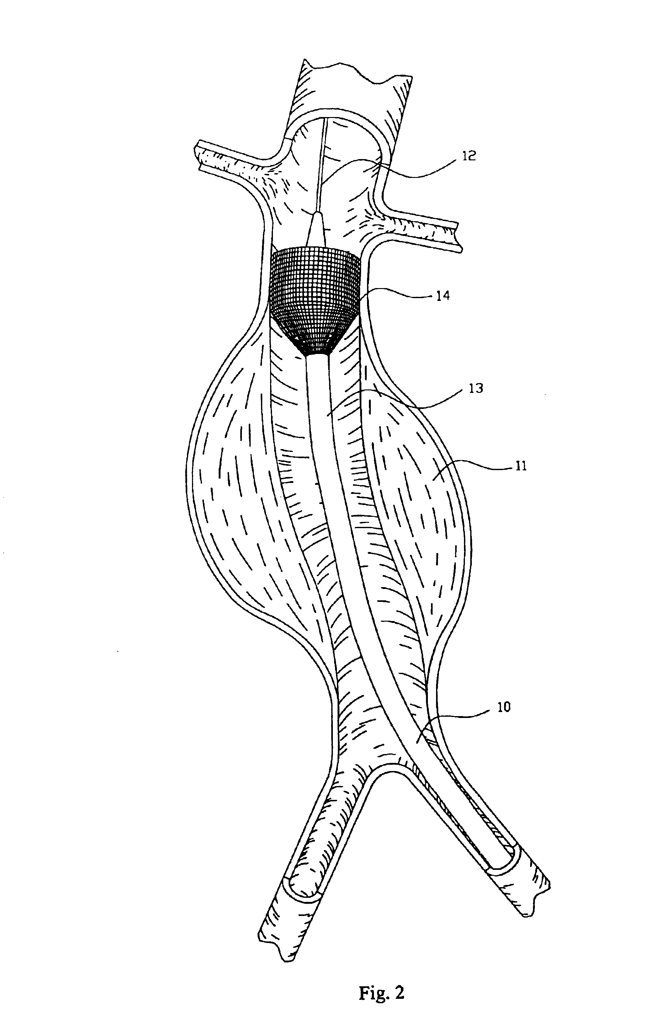
[0037]FIG. 1 depicts an endovascular graft delivery catheter 10 being positioned within an abdominal aortic aneurysm 11 over a guidewire 12. FIG. 2 depicts the initial stage of graft deployment within a vessel. The delivery catheter 10 has a movable cover 13 over the graft. When the cover is pulled proximally the graft 14 expands to contact the internal walls of the vessel. It is contemplated that the graft could be self-expanding or utilize an expanding member such as a balloon or mechanical expander. The process of graft deployment is continued until the graft is fully deployed within the vessel. It is contemplated that the graft could be in either a straight or bifurcated form. FIG. 3 depicts a completely deployed straight graft 14 and FIG. 4 depicts a completely deployed bifurcated graft 15. The guidewire 11 used to deliver and position the graft remains within the vessel for access of the fastener attachment system. One embodiment of the graft scaffolding 16 (stent) is illustra...


PUM


Abstract

Method and apparatus for implanting radially expandable prostheses in the body lumens rely on tacking or anchoring of the prostheses with separately introduced fasteners. The prostheses may be self-expanding or balloon expandable. After initial placement, a fastener applier system is introduced within the expanded prostheses to deploy a plurality of fasteners at at least one prosthesis end, usually as each end of the prosthesis. The fasteners are usually helical fasteners which are delivered from a helical track in the fastener applier by rotation with a rotator wire. The fasteners will be applied singly, typically in circumferentially spaced-apart patterns about the interior of each end of the prosthesis.

Description

RELATED APPLICATION[0001]This application claims the benefit of now abandoned U.S. provisional application Ser. No. 60 / 333,937 filed 28 Nov. 2001.BACKGROUND OF THE INVENTION[0002]The invention relates generally to the attachment of a vascular prosthesis to a native vessel, and in particular, to a method and system of devices for the repair of diseased and / or damaged sections of a vessel.[0003]Description of Related Art. The weakening of a vessel wall from damaged or diseased can lead to vessel dilatation and the formation of an aneurysm. Left untreated, an aneurysm can grow in size and will eventually rupture.[0004]For example, aneurysms of the aorta primarily occur in abdominal region, usually in the infrarenal area between the renal arteries and the aortic bifurcation. Aneurysms can also occur in the thoracic region between the aortic arch and renal arteries. The rupture of an aortic aneurysm results in massive hemorrhaging and has a high rate of mortality.[0005]Open surgical repl...

Claims


Application Information

Patent Timeline
Patent Type & Authority Patents(United States)
IPC IPC(8): A61F2/06A61B17/068A61B17/064A61B17/00
CPCA61B17/064A61B17/068A61F2/06A61F2/07A61B2017/0646A61B2017/0649A61F2/064A61F2/848A61F2002/061A61F2002/065A61F2002/067A61F2002/075Y10S623/903A61F2/90A61B17/10A61B17/072A61B2017/00778A61B2017/00292
Inventor BOLDUC, LEE
Owner MEDTRONIC VASCULAR INC
Learn More