

Clean room
- Summary
- Abstract
- Description
- Claims
- Application Information
AI Technical Summary
Benefits of technology
Problems solved by technology
Method used
Image

Examples
examples
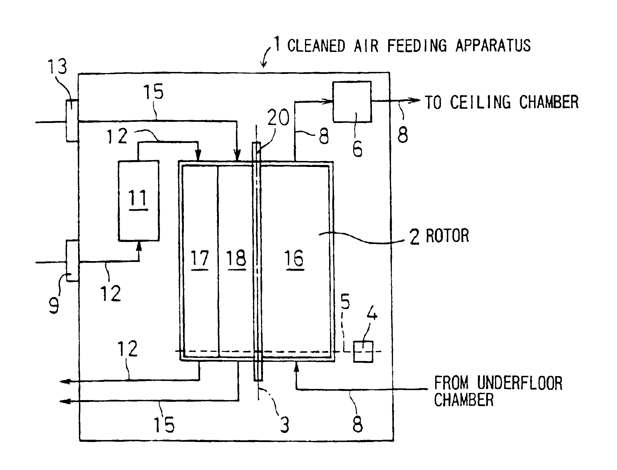
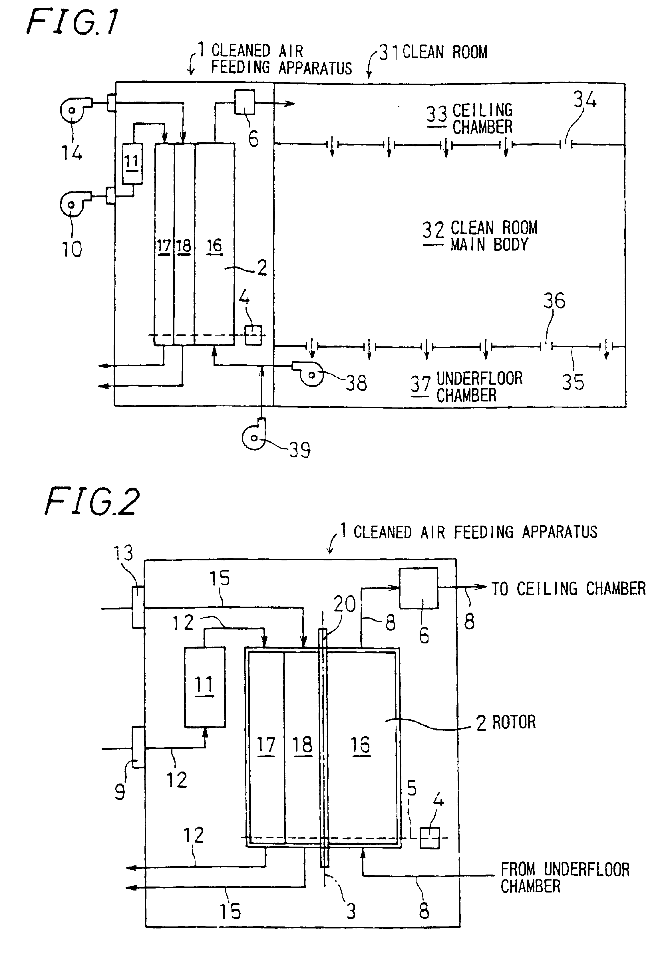
[0048]The air to be cleaned used herein was prepared by mixing 62 to 75 ppb of ammonia as an inorganic gaseous chemical substance and 740 to 800 ppb of N-methylpyrrolidone (NMP) as an organic gaseous chemical substance. The gas to be treated was fed at a flow rate of approximately 3 m3 / min into the cleaned air feeding apparatus 1 equipped with the rotor 2. Regeneration was carried out with air at 175° C. and flowing at a rate of approximately 0.5 m3 / min. Cooling was performed with air at room temperature (20° C.) flowing at a rate of approximately 0.5 m3 / min.
[0049]Because about 1 hour was necessary to attain stable flow of the air to be cleaned and the regenerating air into the cleaned air feeding apparatus 1, sampling of the air to be cleaned and the like for use in analysis was effected 1 hour after setting the apparatus. For the analysis of ammonia, each of the gases was sucked at a rate of 2 L / min for 3 hours by using a diaphragm mini-pump via an impinger (connected in two stage...
PUM
| Property | Measurement | Unit |
|---|---|---|
| Percent by mass | aaaaa | aaaaa |
| Percent by mass | aaaaa | aaaaa |
| Fraction | aaaaa | aaaaa |
Abstract
Description
Claims
Application Information