
Apparatus and methods for monitoring and controlling power amplifier linearity using detected fundamental and harmonic components

a technology of linearity and power amplifier, applied in the field of communication apparatus and methods, can solve the problems of significant affecting the performance of the power amplifier, power amplifiers often encountering non-ideal reflection, and impedance mismatches

Inactive Publication Date: 2005-11-01
TELEFON AB LM ERICSSON (PUBL)
View PDF23 Cites 86 Cited by
  • Summary
  • Abstract
  • Description
  • Claims
  • Application Information

AI Technical Summary

Benefits of technology

[0007]In some embodiments of the invention, the detector circuit may generate the second detector signal without requiring phase information for the harmonic component. For example, the detector circuit may include a directional coupler and a first power detector that generate the first detector signal. The second detector signal may be generated by a combination of a filter, in particular, a bandpass or high p

Problems solved by technology

Power amplifiers often encounter non-ideal reflection arising from impedance mismatches between the power amplifier and transmission medium.
In the case of a wireless terminal power amplifier, for example, impedance mismatches may be caused by a variety of factors, including changes in surroundings caused by motion of the terminal and / or objects in the terminal's environment.
Impedance mismatches can significantly affect performance of a power amplifier.
For example, impedance mismatch may cause the voltage standing wave ratio (VSWR) presented to the power amplifier to be high enough to cause damaging voltages and / or currents at the power amplifier's output.
In addition, large reflected power and high VSWR may lead to performance-degrading phenomena, such as AM / AM and AM / PM distortion.

Method used


Image

  • Apparatus and methods for monitoring and controlling power amplifier linearity using detected fundamental and harmonic components
  • Apparatus and methods for monitoring and controlling power amplifier linearity using detected fundamental and harmonic components
  • Apparatus and methods for monitoring and controlling power amplifier linearity using detected fundamental and harmonic components

Examples


Embodiment Construction

[0015]The present invention now will be described more fully hereinafter with reference to the accompanying drawings, in which illustrative embodiments of the invention are shown. This invention may, however, be embodied in many different forms and should not be construed as limited to the embodiments set forth herein; rather, these embodiments are provided so that this disclosure will be thorough and complete, and will fully convey the scope of the invention to those skilled in the art. As will be appreciated by those of skill in the art, the present invention may be embodied as methods or apparatus.

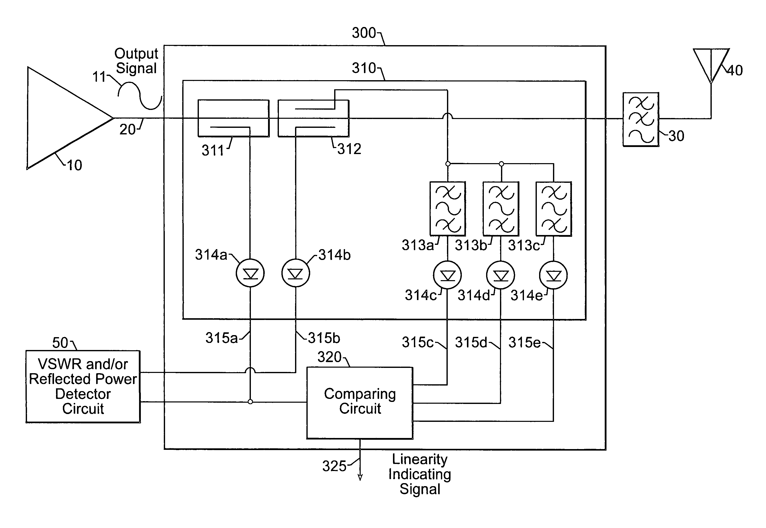
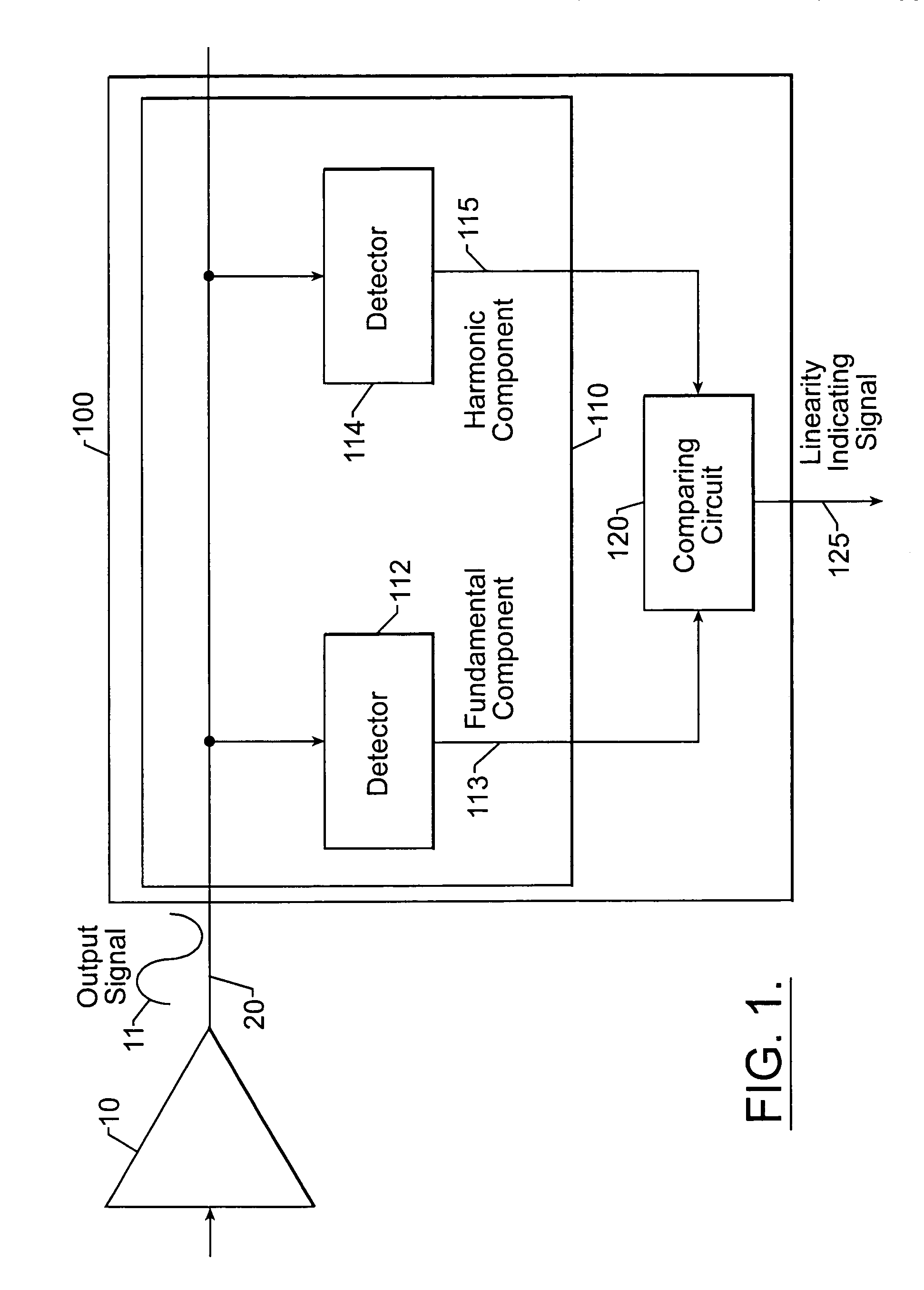
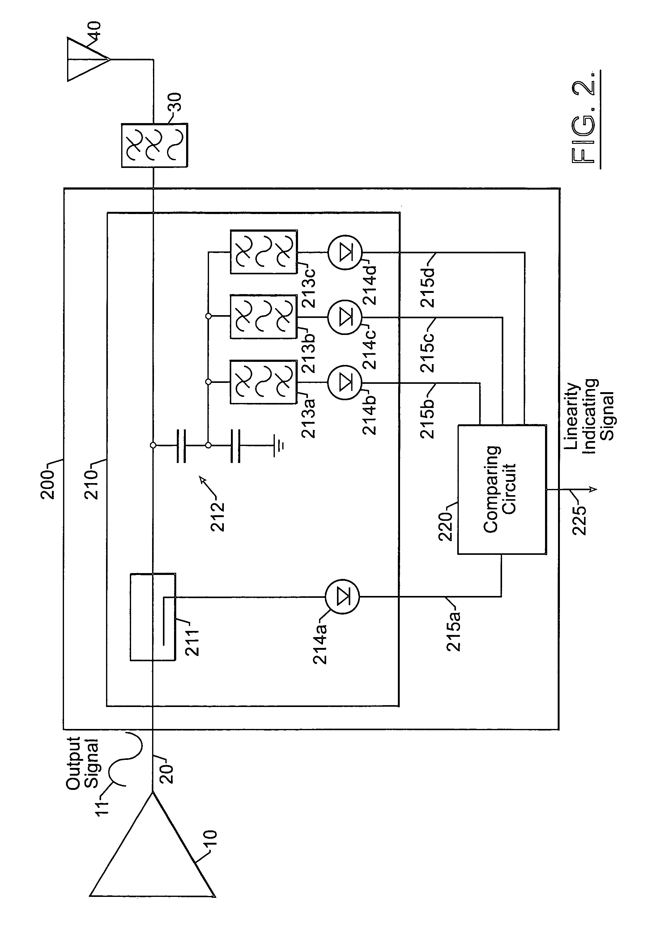
[0016]For power amplifier applications in which an input signal having a desired, fundamental frequency is applied to a power amplifier, non-linear operation (e.g., saturation or clipping) of the amplifier can be detected by comparison of fundamental and harmonic components of the output signal produced by the amplifier. These fundamental and harmonic components can be detected in ways ...


PUM


Abstract

An apparatus for monitoring a power amplifier coupled to a transmission medium includes a detector circuit, coupled to the transmission medium, that generates first and second detector signals corresponding to respective fundamental and harmonic components of a power amplifier output signal produced by the power amplifier. A comparing circuit is coupled to the detector circuit and compares the first and second detector signals. The comparing circuit, responsive to a comparison of the first and second detector signals, may generate a signal that indicates linearity of the power amplifier. In some embodiments, the detector circuit may generate the second detector signal without requiring phase information for the harmonic component. In other embodiments, a control circuit controls linearity of the power amplifier responsive to comparison of the first and second detector signals, for example, by controlling power amplifier bias and / or input signal level based on the comparison. Related methods are also discussed.

Description

BACKGROUND OF THE INVENTION[0001]The present invention relates to communications apparatus and methods, and more particularly, to power amplifier monitoring and control apparatus and methods.[0002]Communications apparatus often include a power amplifier that is used to amplify a signal to appropriate levels for transmission, for example, in free space or on a transmission line. For example, wireless terminals (e.g., cellular telephones and other wireless-capable devices) typically include a power amplifier that is used to amplify a radio frequency (RF) signal for transmission by an antenna.[0003]Power amplifiers often encounter non-ideal reflection arising from impedance mismatches between the power amplifier and transmission medium. In the case of a wireless terminal power amplifier, for example, impedance mismatches may be caused by a variety of factors, including changes in surroundings caused by motion of the terminal and / or objects in the terminal's environment. Such changes ma...

Claims


Application Information

Patent Timeline
IPC IPC(8): H03F1/32H03F1/02H03F1/34H04B1/04
CPCH03F1/0272H03F1/3247H03F1/345H04B1/0475H04B2001/0433H03F1/34H03F3/24
Inventor PEHLKE, DAVID R.MEADOWS, RONALD
Owner TELEFON AB LM ERICSSON (PUBL)
Learn More