Local oscillator leakage control in direct conversion processes

a local oscillator and leakage control technology, applied in the field of wireless communication, can solve problems such as intermodulation distortion, weak signal detection more difficult, and distortion of unwanted signals at the output of devices

Inactive Publication Date: 2005-11-01
QUALCOMM INC
View PDF5 Cites 93 Cited by
  • Summary
  • Abstract
  • Description
  • Claims
  • Application Information

AI Technical Summary

Benefits of technology

[0040]In another embodiment, the system incorporates a LO generator, a frequency band selection mechanism, and a configuration selection mechanism. The LO generator has one or more configurations, and includes a mixer configured to mix a VCO frequency with a divided-down version of the VCO frequency. Each configuration is associated with a freque

Problems solved by technology

Desense occurs when a very strong interfering signal overloads the receiver and makes the detection of weaker signals more difficult.
Distortion is the presence of unwanted signals at the output of devices in the RF path of a receiver.
Intermodulation distortion is the result of two or more signals mixing together to produce additional unwanted distortion within the signal bandwidth.
Such leakage may be transmitted by the transceiver antenna as spurious emissions, which may interfere with other devices.
In addition, LO leakage may be reflected back into the receiver itself and may desense the receiver if not removed prior to demodulation.
Jammer leakage occurs when a jammer signal leaks to an LO input or output of a device within a receiver.
Such leakage may mix with the jammer signal to produce undesired signals, such as DC signal levels that are proportional to the amplitude modulation (AM) component of the jammer signal.
Wireless communications have not yet been standardized on an international, or even intranational, basis.
Yet, given the current multiplicity of modulation standards and associated frequency bands, dual mode and dual band phones offer subscribers at most a limited compatibility with communications systems of the world.
The need for an IF filter for each mode is a significant drawback of receiver 101.
Each IF filter increases the cost of

Method used


Image

  • Local oscillator leakage control in direct conversion processes
  • Local oscillator leakage control in direct conversion processes
  • Local oscillator leakage control in direct conversion processes

Examples


Embodiment Construction

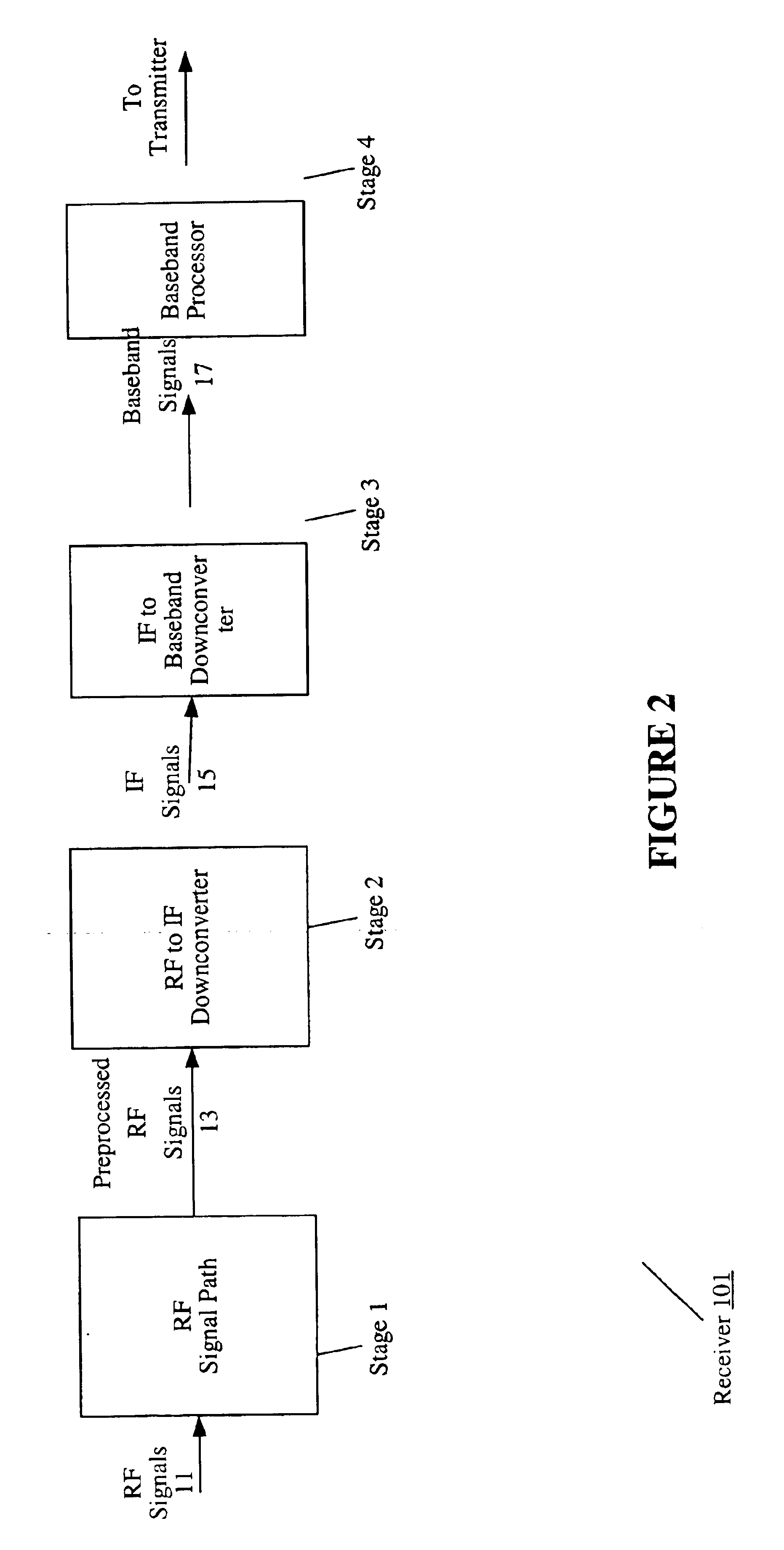
[0050]FIG. 4 is a high-level block diagram of direct downconversion receiver 200 according to an embodiment of the present invention. Receiver 200 comprises an RF signal path 210, a direct downconverter 220, and a baseband processor 230.

[0051]RF signal path 210 receives RF signals 201. RF signals 201 may comprise signals modulated in multiple modes and conveyed in multiple frequency bands. RF signal path 210 may include selection mechanisms to select among various modes and various bands. Additionally, RF signal path 210 may include amplifiers or filters to prepare RF signals 201 for further processing. Such prepared signals are designated as preprocessed RF signals 215 in FIG. 4. Direct downconverter 220 receives preprocessed RF signals 215 from RF signal path 210 and downconverts such signals to baseband signals 225.

[0052]Baseband processor 230 may perform subsequent processing on baseband signals 225, such as, for example, DC cancellation, matched and jammer filtering, sample dec...


PUM


Abstract

A system and method for generating a local oscillator (LO) frequency in a zero intermediate frequency (IF) receiver or transmitter is presented. A signal is received from a voltage controlled oscillator (VCO). The signal has a VCO frequency. The VCO frequency is divided by a number N to produce a signal having a divided-down frequency. The signal having the VCO frequency is then mixed with the signal having the divided-down frequency to produce an output signal having an output frequency. Local oscillator leakage is reduced. Thus, the receiver or transmitter may operate in multiple wireless communication bands and modes and meet the associated specifications.

Description

RELATED APPLICATIONS[0001]This application claims priority to Provisional application No. 60 / 261,714, filed on Jan. 12, 2001. This application is a continuation of U.S. patent application Ser. No. 09 / 797,745 filed on Mar. 1, 2001, now abandoned.BACKGROUND[0002]1. Field[0003]This invention relates in general to wireless communications. Specifically, this invention relates to systems and methods for direct conversion transceivers.[0004]2. Background and Related Art[0005]The field of communications has experienced a tremendous growth due in large part to the improved capabilities of wireless devices. Wireless devices employ radio waves to enable distant communications without the physical constraints of wire-based systems. Information, such as voice, data, or paging information, is conveyed by radio waves transmitted over predetermined frequency bands. Allocation of available frequency spectra is regulated to ensure that numerous users may communicate without undue interference.[0006]I...

Claims


Application Information

Patent Timeline
IPC IPC(8): H03D3/00H03L7/183G01N33/14H04B1/30H04B1/40
CPCH03D3/008H03D3/009G01N33/14
Inventor PETERZELL, PAUL E.MALDONADO, DAVIDGARD, KEVINSEE, PUAY HOEDUNWORTH, JEREMYSAHOTA, GURKANWAL
Owner QUALCOMM INC
Why Eureka
Try Eureka