High-gain conformal array antenna

a conformal array and antenna technology, applied in the field of high-gain conformal array antennas, can solve the problems of large, complex and expensive circuitry to make them work, occupying a significant amount of space, and requiring large power for phase shifters or beam-forming networks

Active Publication Date: 2005-11-01
LOCKHEED MARTIN CORP
View PDF7 Cites 58 Cited by
  • Summary
  • Abstract
  • Description
  • Claims
  • Application Information

AI Technical Summary

Benefits of technology

[0018]A more complete understanding of the present invention may be derived by referring to the d...

Problems solved by technology

The problem with traditional phased array antennas is that they require large, complex and expensive circuitry to make them work.
As one skilled in the art w...

Method used


Image

  • High-gain conformal array antenna
  • High-gain conformal array antenna
  • High-gain conformal array antenna

Examples


Embodiment Construction

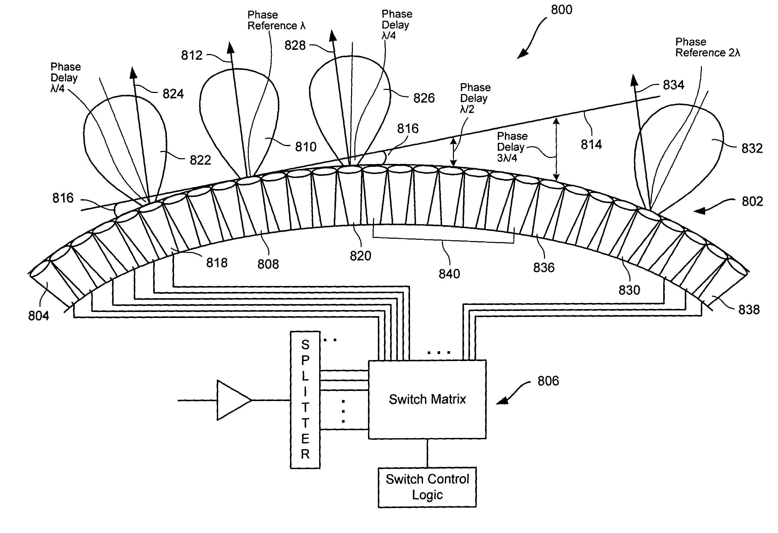
[0035]The present invention relates generally to an antenna array, and more particularly to a high-gain conformal antenna array that can steer its beam direction without the use of phase shifters and beamformer circuitry. Instead, the beam is steered by selecting an array element that points most nearly in the general direction that is desired. One or more arrays of elements that are contiguous to the selected element are enabled. Further, in one embodiment, non-contiguous elements may be selected to help the antenna gain. This ensemble of elements creates a high-gain directional beam in the direction of that beam of the center element.

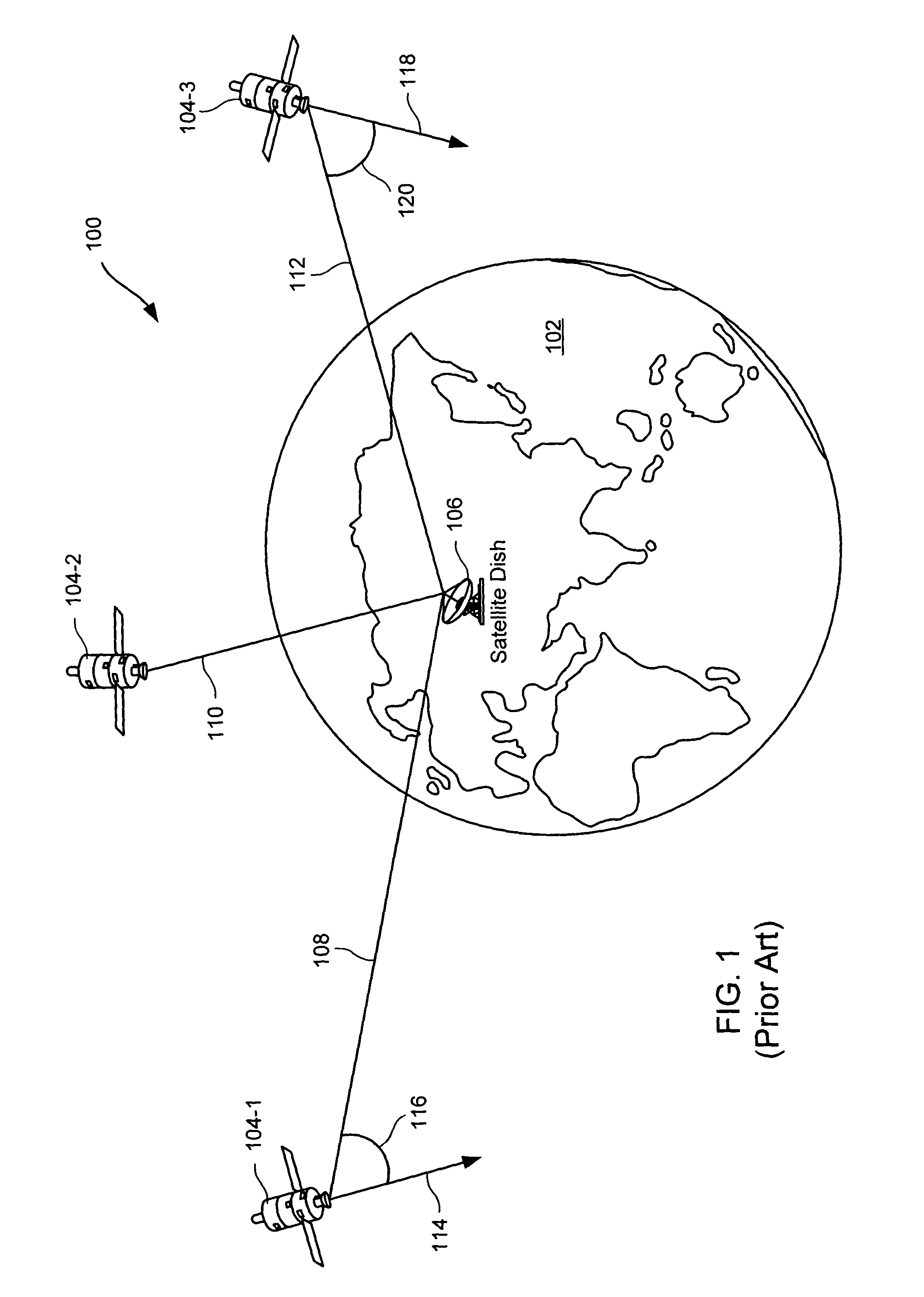
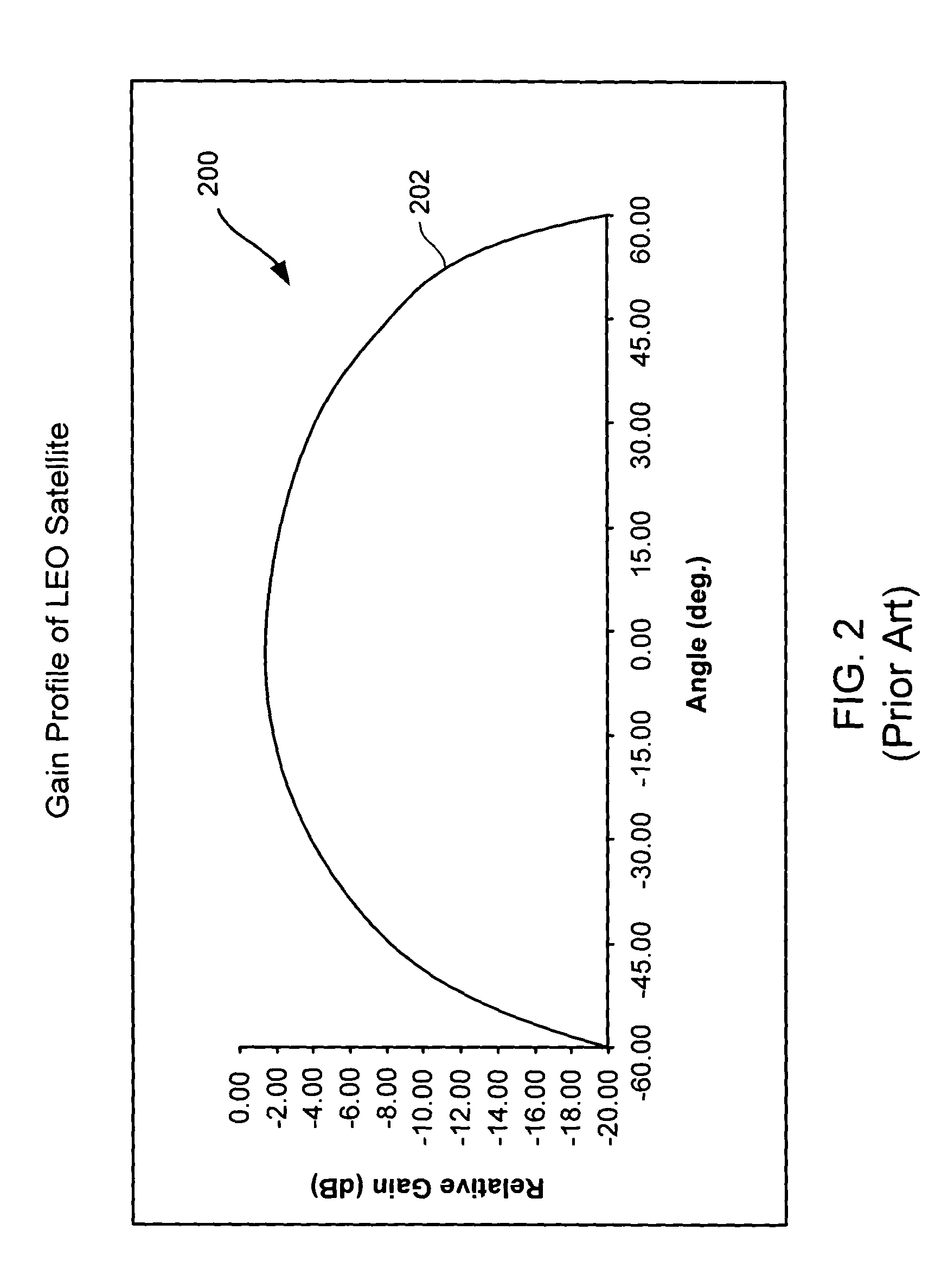
[0036]One environment in which it is favorable to use “steerable” antenna arrays is satellite communications, and in particular with low earth orbit (LEO) and medium earth orbit (MEO) satellites. As one skilled in the art will appreciate, LEO satellites, such as those launched by NASA and other entities, are used for a variety of purposes. For example...


PUM


Abstract

An antenna array system comprising a plurality of antenna elements organized in an array and configured to form a non-planar shaped antenna array surface. The antenna array system further comprises switching circuitry configured to switch each of the plurality of antenna elements on or off based on control signals. In one embodiment, the antenna array system is configured such that the antenna beam direction can be steered in a first direction by switching on a first set of antenna elements, and the antenna beam direction can be steered in a second direction by switching on a second set of antenna elements. In one embodiment, the second set of antenna elements can include one or more antenna elements from the first set of antenna elements, or the second set of antenna elements may not include any antenna elements from the first set.

Description

BACKGROUND OF THE INVENTION[0001]The present invention relates generally to an antenna array, and more particularly to a high-gain conformal antenna array that can steer its beam direction without the use of phase shifters and beamformer circuitry.[0002]It is often desirable to have antenna arrays that are “steerable,” so that the antenna can be used to communicate while the antenna is attached to a moving object. Typically, these “steerable” antennas are phased array antennas. A phased array antenna usually has a non-mechanically steered array of radiators. The radiating elements are passive devices (e.g., dipoles or feed horns), and may include active devices, such as amplifiers. The steering of the beam is carried out by varying the phase (and amplitude for full side lobe control) of the signal in each radiating element. For a passive device, the phase control typically is achieved in a feed assembly placed between a high-power amplifier and the radiating elements, and for an act...

Claims


Application Information

Patent Timeline
IPC IPC(8): H01Q13/00H01Q1/28H01Q3/24H01Q21/06H01Q25/00
CPCH01Q1/288H01Q3/24H01Q21/064H01Q25/00
Inventor CHETHIK, FRANKBREEN, JR., RICHARD
Owner LOCKHEED MARTIN CORP
Why Eureka
Try Eureka