Optical digital external modulator

Inactive Publication Date: 2005-11-01
JDS UNIPHASE CORP
View PDF26 Cites 34 Cited by
  • Summary
  • Abstract
  • Description
  • Claims
  • Application Information

AI Technical Summary

Benefits of technology

[0016]The instant invention relates to an optical digital external modulator having a series cascaded arrangement and biasing means for providing improved trans

Problems solved by technology

Modulation bandwidth is typically limited by the fact that the RF signal travels more slo

Method used


Image

  • Optical digital external modulator
  • Optical digital external modulator
  • Optical digital external modulator

Examples


Example

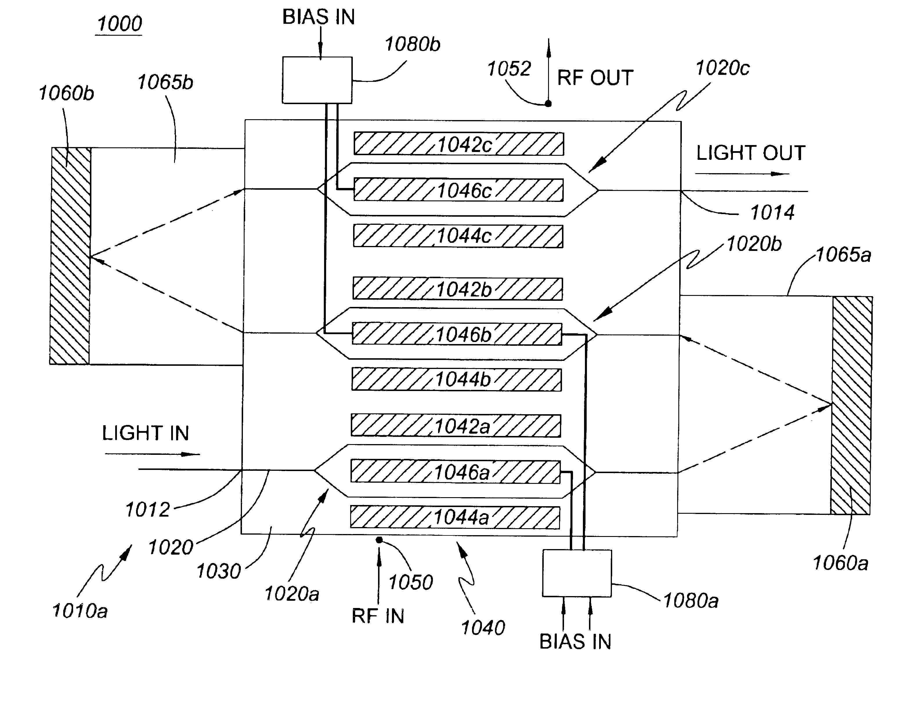
[0045]Referring to FIG. 3, there is shown a schematic diagram of an optical digital external modulator 300 that includes an optical waveguide 320 formed in an x-cut lithium niobate (LiNbO3) substrate 330. The optical waveguide 320 includes a first Y-branch 322, a first interferometer arm 324a / 324b, a second interferometer arm 326a / 326b, and a second Y-branch 328, which collectively form an integrated Mach-Zehnder interferometer. At the end of the substrate 330 opposing the input / output end 310, the waveguide 320 and a mirror 360 form first 324c and second 326c directional couplers. A traveling-wave electrode structure 340 is provided near the optical waveguide 320 such that the first part of the first interferometer arm 324a is disposed between ground electrode 342a and hot electrode 346a, while the first part of the second interferometer arm 326a is disposed between ground electrode 344a and hot electrode 346a. Similarly, the second part of the first interferometer arm 324b is disp...


PUM


Abstract

An optical digital external modulator having a cascaded arrangement of interferometers is provided. The optical modulator includes an electrode structure for applying an electric field to each interferometer in the cascade and biasing circuitry coupled to the electrode structure for biasing each interferometer at a predetermined bias point. In particular, each predetermined bias point is selected to be above quadrature and for providing improved transmission performance of digital data signals. Preferably, the modulator has a reflective design that helps to increase the modulation bandwidth, lower the drive voltage, and reduce size.

Description

CROSS-REFERENCE TO RELATED APPLICATIONS[0001]This application claims the benefit of U.S. Provisional Application No. 60 / 474,771, filed May 30, 2003, entitled “Improved Optical Digital External Modulator Using A Series Cascaded Arrangement And Biasing Means” which is incorporated herein by reference for all purposes.MICROFICHE APPENDIX[0002]Not Applicable.TECHNICAL FIELD[0003]The present application relates generally to optical modulators, and in particular, to optical digital external modulators.BACKGROUND OF THE INVENTION[0004]Optical modulators are currently used in optical communication systems to convert electrical signals representing data or voice into modulated optical signals. Optical modulators are typically based on direct or external modulation. With direct modulation, the optical source is turned on and off at intervals. With external modulation, the optical source is operated continuously and its output light is modulated using an optical external modulator.[0005]Optica...

Claims


Application Information

Patent Timeline
IPC IPC(8): G02F1/01G02F1/225G02F1/035
CPCG02F1/225G02F2201/16G02F2203/02G02F2203/19
Inventor WOOTEN, EDKISSA, KARLMCBRIEN, GREGORY J.MUNKS, TIMOTHY C.FINCH, ANDREW
Owner JDS UNIPHASE CORP
Why Eureka
Try Eureka