Head position control method and disk storage device

a control method and disk technology, applied in the direction of maintaining head carrier alignment, light beam reproducing, instruments, etc., can solve the problems of increasing the speed of the track accessing time, reducing the phase margin of the control system, and detecting the head speed accurately. , to achieve the effect of simple operation

Inactive Publication Date: 2005-11-01
TOSHIBA STORAGE DEVICE CORP
View PDF2 Cites 4 Cited by
  • Summary
  • Abstract
  • Description
  • Claims
  • Application Information

AI Technical Summary

Benefits of technology

[0031]By this, the head speed can be detected accurately with a simpler operation.
[0032]Also in the present invention, it is preferable that the step of controlling the actuator comprises a step of generating the target speed based on the difference between the target position and the above mentioned detected current positio

Problems solved by technology

However if there is an error in the information of the detected head position, the high frequency component of the positional error is emphasized as the error of the speed by the differential operation.
Such an error of the detection speed and the actual speed drops the follow up accuracy to the target spe

Method used


Image

  • Head position control method and disk storage device
  • Head position control method and disk storage device
  • Head position control method and disk storage device

Examples


Embodiment Construction

[0045]Embodiments of the present invention will now be described in the sequence of disk storage device, head speed detection method, and other embodiments, but the present invention is not restricted by the following embodiments.

[Disk Storage Device]

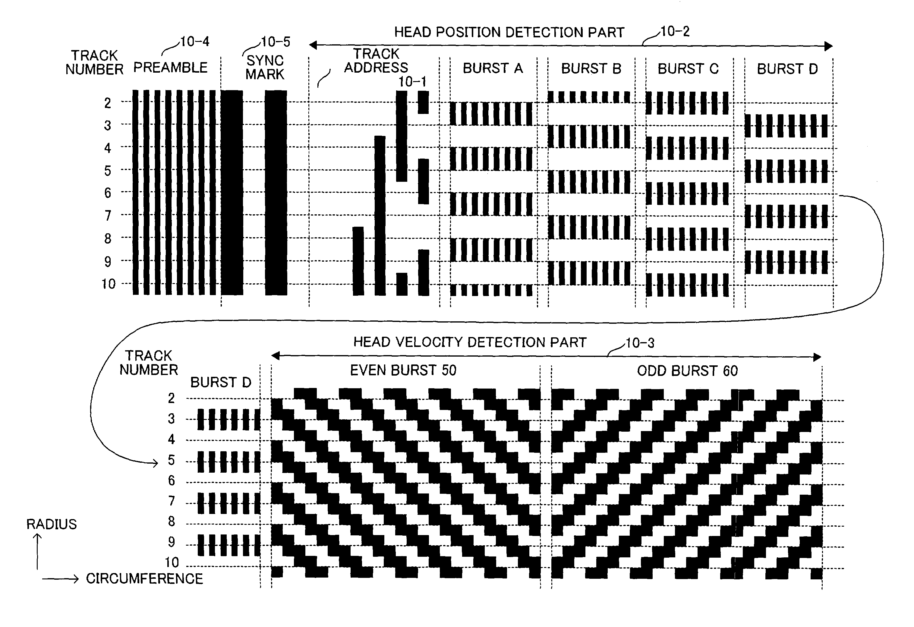
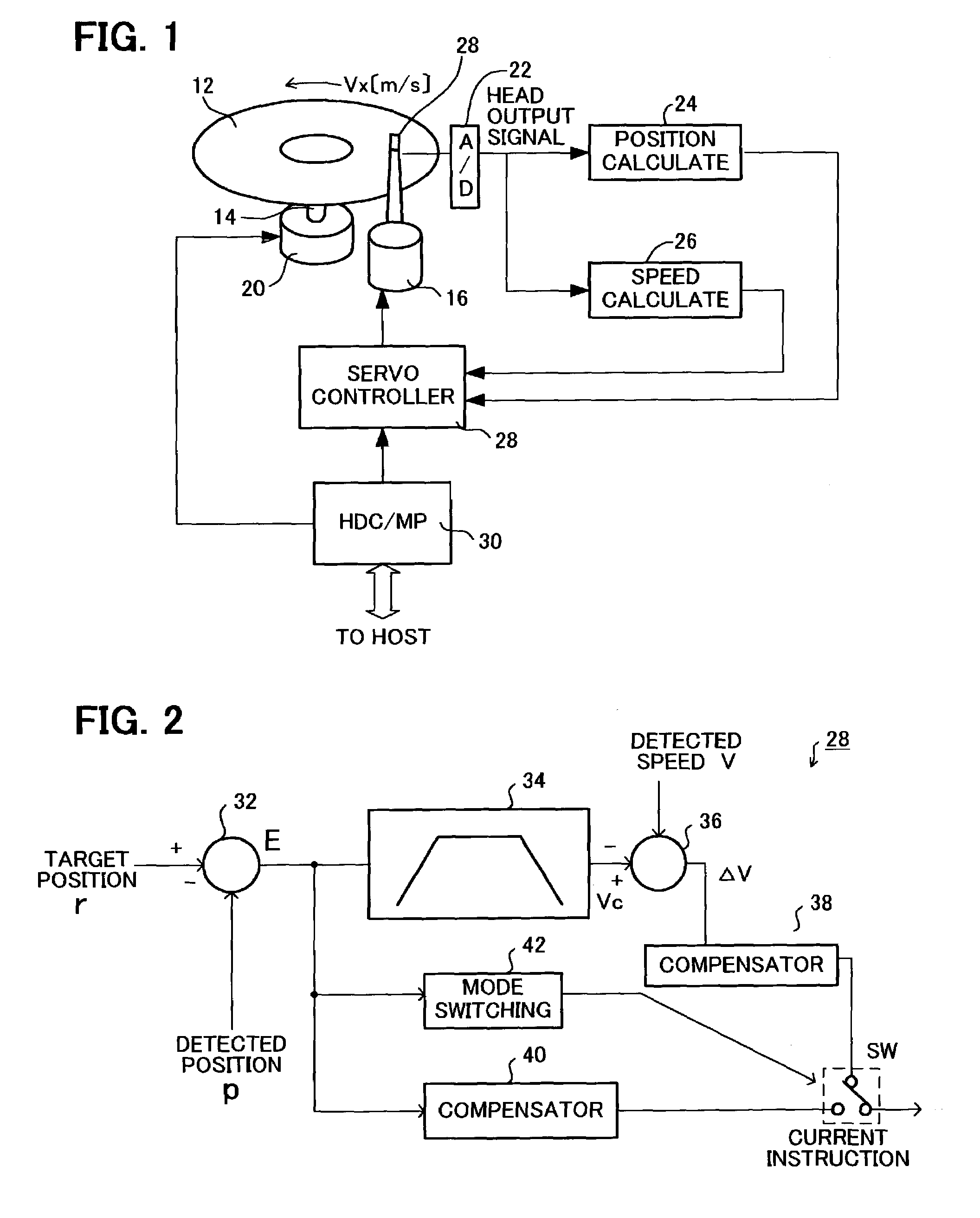
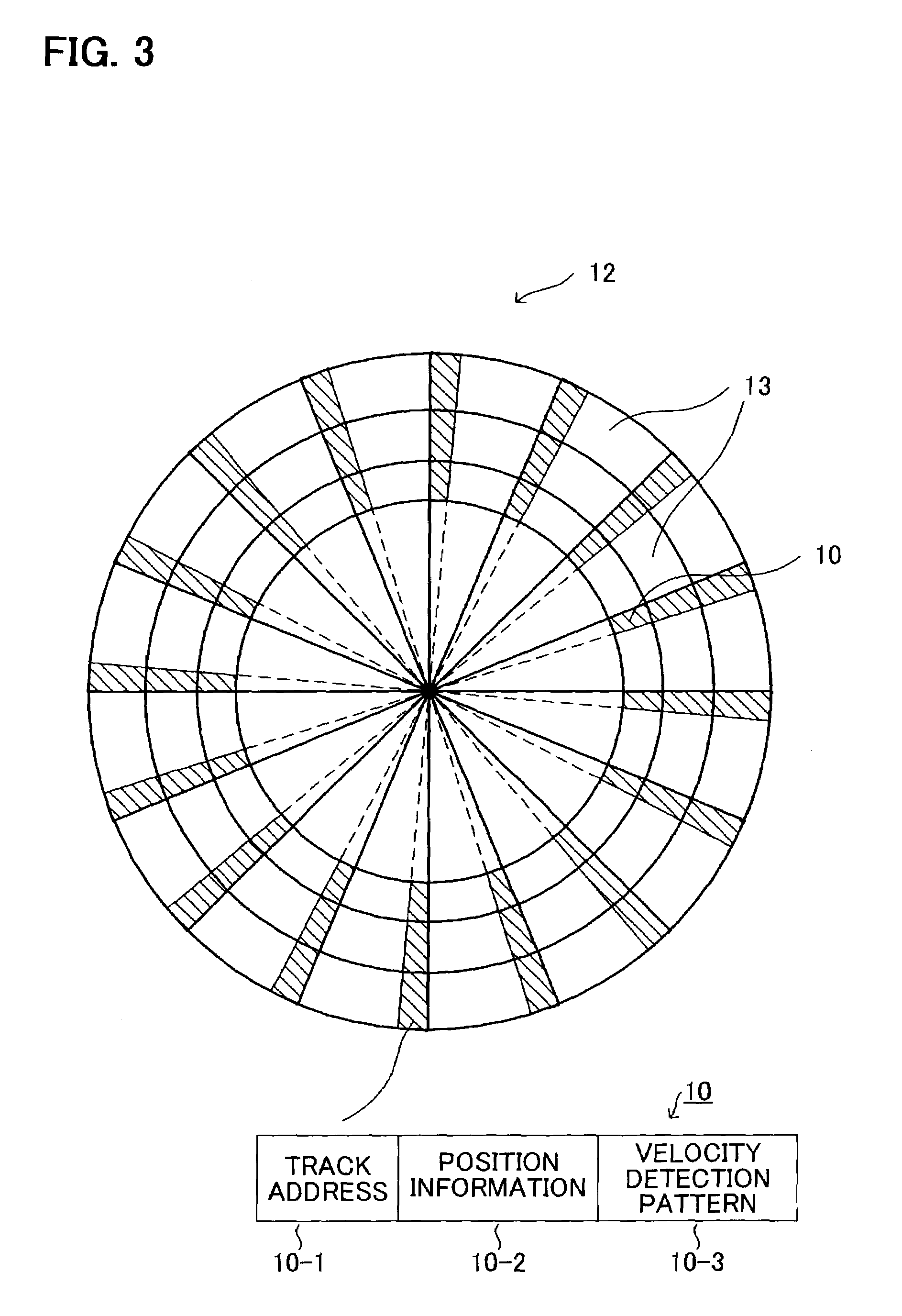
[0046]FIG. 1 is a diagram depicting the disk storage device according to an embodiment of the present invention, FIG. 2 is a functional block diagram depicting the servo controller in FIG. 1, FIG. 3 is a top view of the magnetic disk in FIG. 1, and FIG. 4 is a diagram depicting the configuration of the servo area in FIG. 3.

[0047]FIG. 1 shows a magnetic disk device as the disk storage device. As FIG. 1 shows, the magnetic disk 12, which is a magnetic storage medium, is installed on the rotation axis 14 of the spindle motor 36. The spindle motor 36 rotates the magnetic disk 12. The actuator 16 has a magnetic head 18 at the tip, and moves the magnetic head 18 in the radius direction of the magnetic disk 12.

[0048]The actuator 16 is comprise...


PUM


Abstract

A head position control method controls the speed of the head using the position and the speed detected from the servo information on the disk and directly detects the head speed. The speed detection pattern is assigned to the servo area of the disk, and the speed of the head is detected at the frequency of the regeneration signal. Therefore the speed of the head can be directly detected at the timing of the servo reading. By this, information on the head speed can be obtained with less error. Since there is no delay in the speed detection, the phase margin of the control system increases and stability improves.

Description

BACKGROUND OF THE INVENTION[0001]1. Field of the Invention[0002]The present invention relates to a head position control method of a disk storage device and a disk storage device which uses a disk as an information recording medium, moves a head in a radius direction of the disk, and reads information recorded on the disk, and more particularly to a head position control method and disk storage device for reading servo information of the disk and controlling the position of the head.[0003]2. Description of the Related Art[0004]Information storage devices using such recording medium as a magnetic disk, optical disk, and magneto-optical disk are widely used. In such an information storage device, a read or read / write head is positioned at a predetermined track of a disk for reading or writing data.[0005]FIG. 10 is a diagram depicting the servo-information of a conventional disk, FIG. 11 is a diagram depicting a head positioning control system of a conventional disk device, and FIG. 12...

Claims


Application Information

Patent Timeline
IPC IPC(8): G11B19/28G11B5/55G11B5/596G11B7/085G11B7/007G11B21/08G11B11/105
CPCG11B5/5526G11B5/596G11B7/08529G11B19/28G11B7/00736G11B11/10565
Inventor SHIMATANI, KEIJI
Owner TOSHIBA STORAGE DEVICE CORP
Why Eureka
Try Eureka