Switching power supply

a technology of switching power supply and cooling channel, which is applied in the direction of power conversion systems, dc-dc conversion, cooling/ventilation/heating modification, etc., can solve the problem of large space required to install such a switching power supply, and achieve the effect of simple preparation process, reduced number of parts required for the formation of coolant channels, and easy demolding

Active Publication Date: 2005-11-01
TDK CORPARATION
View PDF13 Cites 41 Cited by
  • Summary
  • Abstract
  • Description
  • Claims
  • Application Information

AI Technical Summary

Benefits of technology

[0012]Moreover, it is preferable that an opening portion is formed on a back side of the pedestal portion, and the coolant channel is defined by means of a channel sidewall integrally provided upright on the back side of the pedestal portion and of a cover plate which covers the opening portion. In this case, the coolant channel is formed of two parts of the cover plate and the base plate in which the channel sidewall is formed. Hence, the number of parts required for the formation of the coolant channel is reduced, and preparation process of the switching power supply is simple.
[0013]Further, it is preferable that, on the cover plate, an inlet pipe through which the coolant is flown into the coolant channel and an outlet pipe through which the coolant is flown out of the coolant channel, the inlet and outlet pipes extending in a normal direction of the cover plate, are integrally molded. In this case, water leakage in joint portions of the cover plate with the inlet and outlet pipes is suppressed. Moreover, when the inlet and outlet pipes are integrally molded to the cover plate by casting, demolding will be easy by releasing the mold in a direction of a normal of the cover plate.

Problems solved by technology

Accordingly, a larger space is required to install such a switching power supply.

Method used


Image

  • Switching power supply
  • Switching power supply
  • Switching power supply

Examples


Embodiment Construction

[0023]A preferred embodiment of the present invention will be detailed hereinbelow with reference to the accompanying drawings. Note that the same reference numerals are applied to the same elements, and overlapping explanation thereof will be omitted.

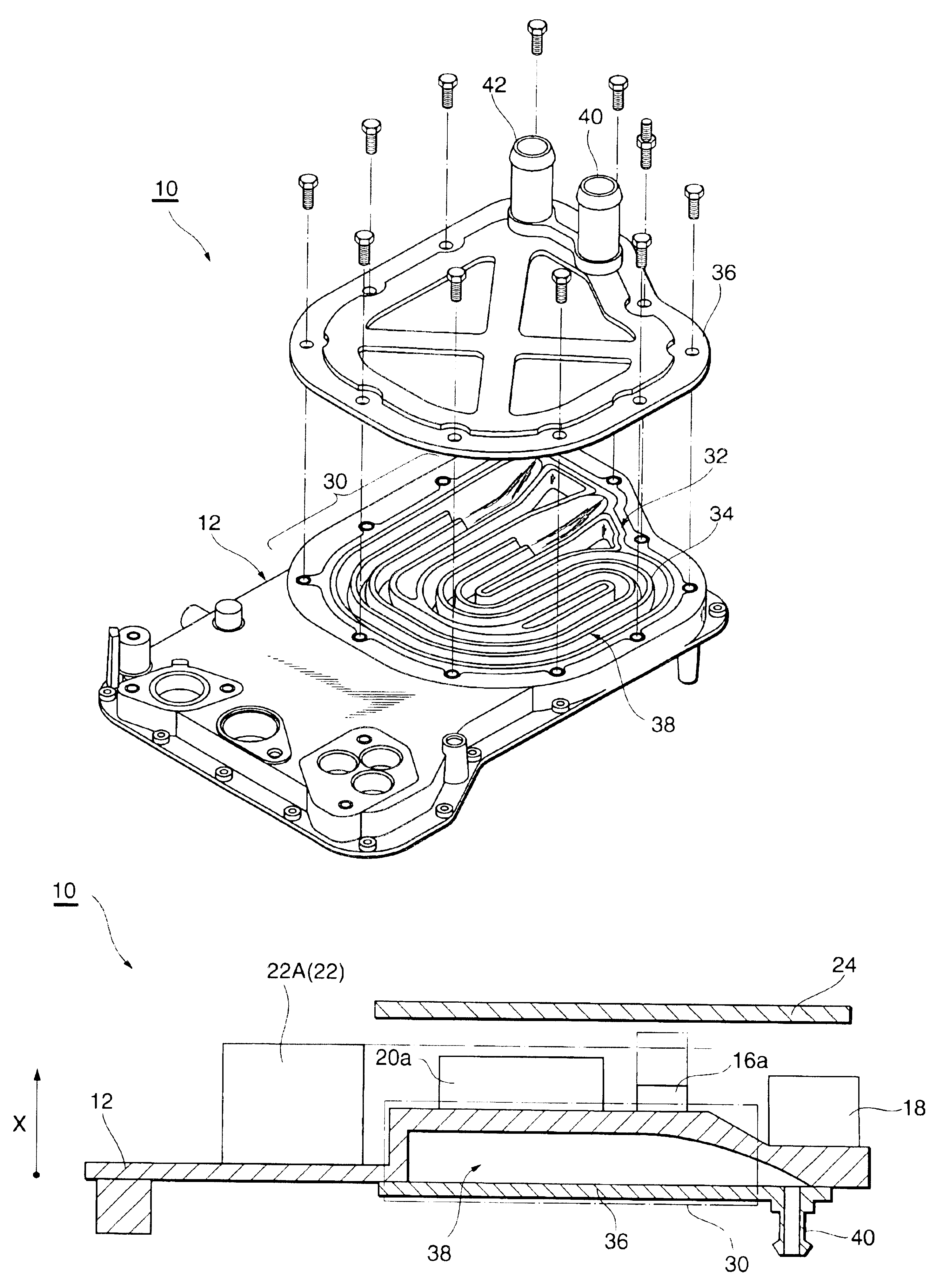
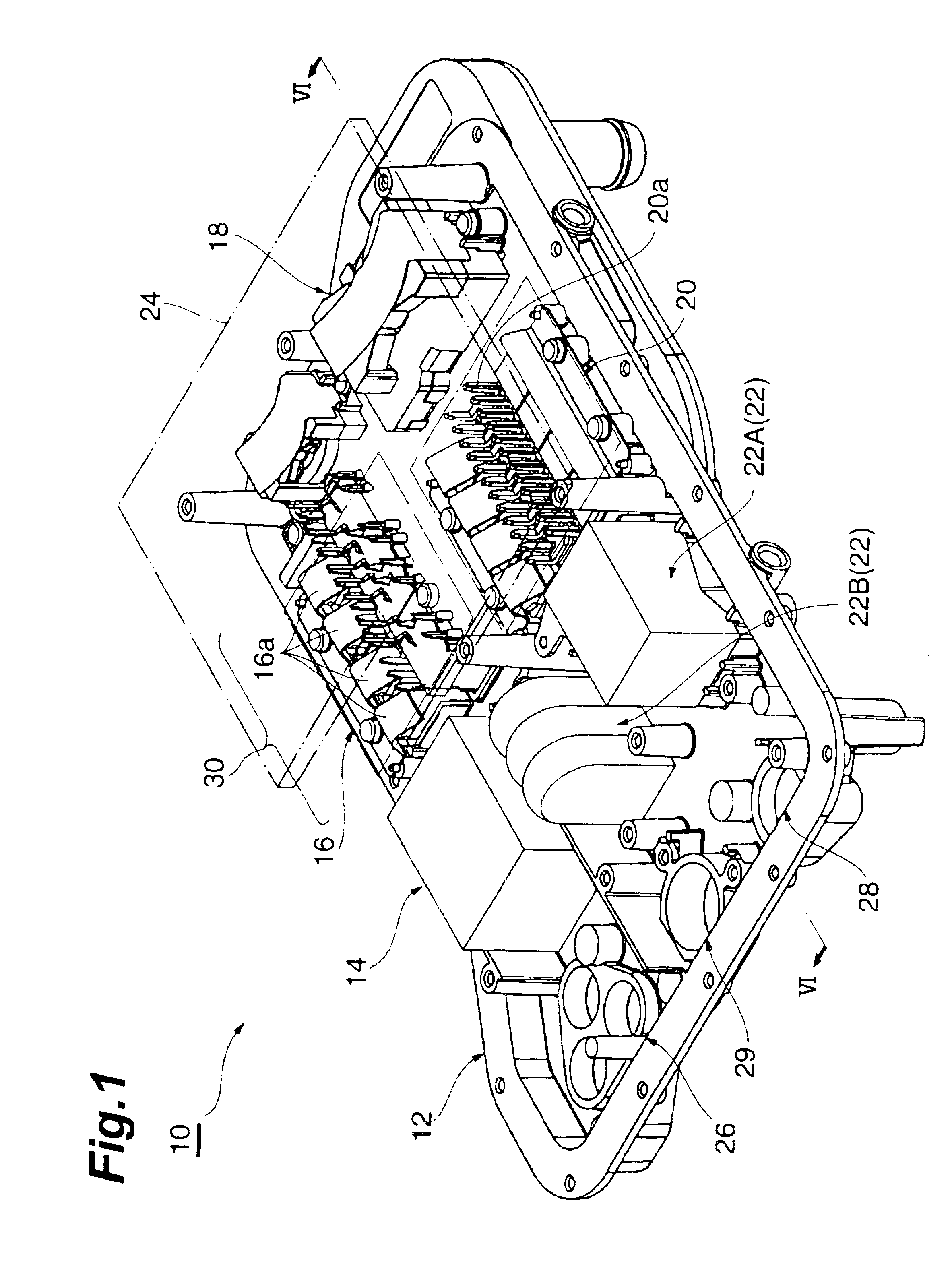
[0024]FIG. 1 is a perspective overview of a switching power supply 10 according to an embodiment of the present invention. The switching power supply 10 is a so-called DC—DC converter applied to a hybrid car and the like, and is a device which steps down an input voltage sent from an on-vehicle battery, and stabilizes the voltage to send it out to on-vehicle equipment such as power windows, headlights, and audio equipment, as well as to a motor and the like.

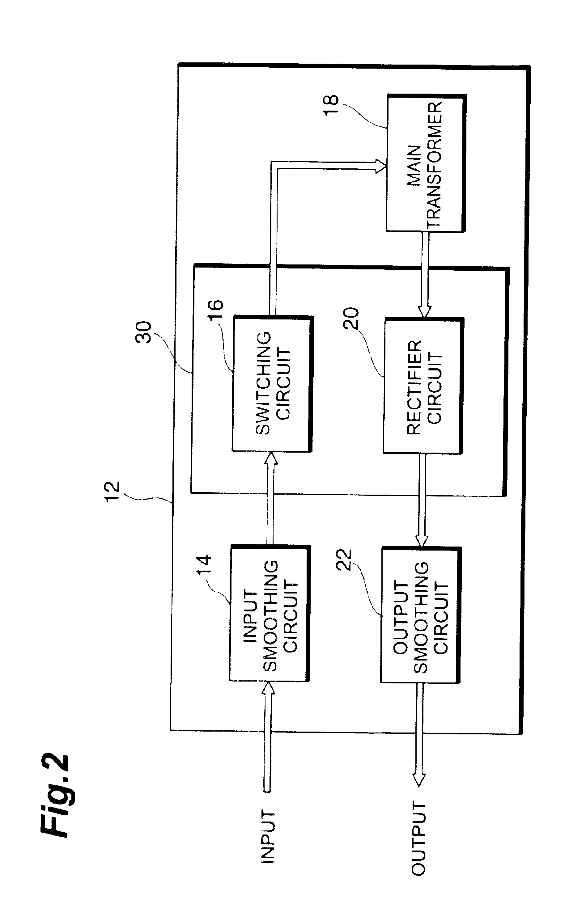
[0025]The switching power supply 10 includes, as main components, a base plate 12, an input smoothing circuit 14 for removing noises of an input voltage, a switching circuit 16 for converting a direct current into an alternating current, a main transformer 18 which performs voltage ...


PUM


Abstract

A switching power supply includes a switching circuit, a main transformer, a rectifier circuit, and an output smoothing circuit, which are mounted on a base plate. Voltage transformation of an inputted direct current voltage is performed through collaboration among the above. A pedestal portion is formed on the base plate, and a channel to cool down electronic parts such as a diode is formed inside the pedestal portion. Since the channel is thus formed inside the pedestal portion, the device will not be larger-sized even when the channel is formed. Moreover, at least any of a switching element and a diode is mounted on the pedestal portion, and a choke coil is mounted in a region other than a region where the pedestal portion is formed. Therefore, even with the pedestal portion, it is significantly suppressed for the device to be larger-sized.

Description

BACKGROUND OF THE INVENTION[0001]1 . Field of the Invention[0002]The present invention relates to a switching power supply, and particularly to a switching power supply used as a DC—DC converter.[0003]2 . Related Background of the Invention[0004]In recent years, there have been growing demands for energy saving and environmental conservation, and, as one of what reflect such demands, hybrid cars have been put into practical application. A hybrid car is a car that utilizes, as its power source, a conventional internal combustion engine and an electric motor (motor for a hybrid car) combined therein. The motor for a hybrid car is capable of recovering electric energy by performing power regeneration when the speed is reduced or the like. The regenerated power as well as power generated by utilizing outputs of the internal combustion engine are stored in a battery.[0005]A voltage supplied from a battery is stepped down in a DC—DC converter to be distributed to on-vehicle equipment such...

Claims


Application Information

Patent Timeline
Patent Type & Authority Patents(United States)
IPC IPC(8): H02M3/28H02M1/00H02M3/24H05K7/20H02M3/00
CPCH02M3/00H05K7/20927H02M3/003
Inventor TSUCHIYA, TAKAHIROSUNAMI, RYOJI
Owner TDK CORPARATION
Why Eureka
Try Eureka