System and method for partitioning a computer system into domains

Inactive Publication Date: 2005-11-01
FUJITSU LTD
View PDF25 Cites 53 Cited by
  • Summary
  • Abstract
  • Description
  • Claims
  • Application Information

AI Technical Summary

Problems solved by technology

However, conventional domain partitioning has the drawback that the domain partitioning can become deleteriously affected by software and hardware errors of any one domain.
Second, a malicious user (a “hacker”) can intention

Method used


Image

  • System and method for partitioning a computer system into domains
  • System and method for partitioning a computer system into domains
  • System and method for partitioning a computer system into domains

Examples


Embodiment Construction

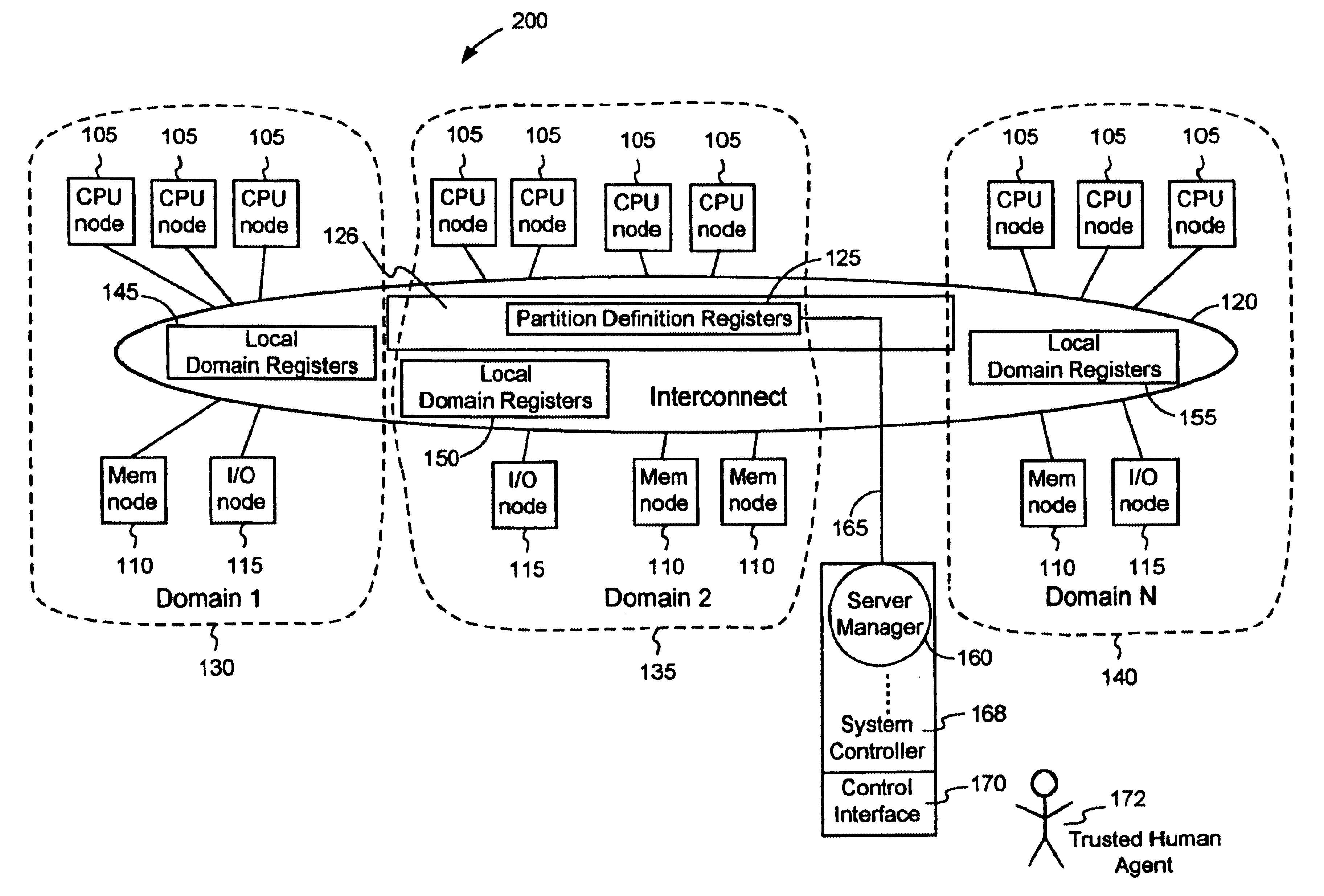
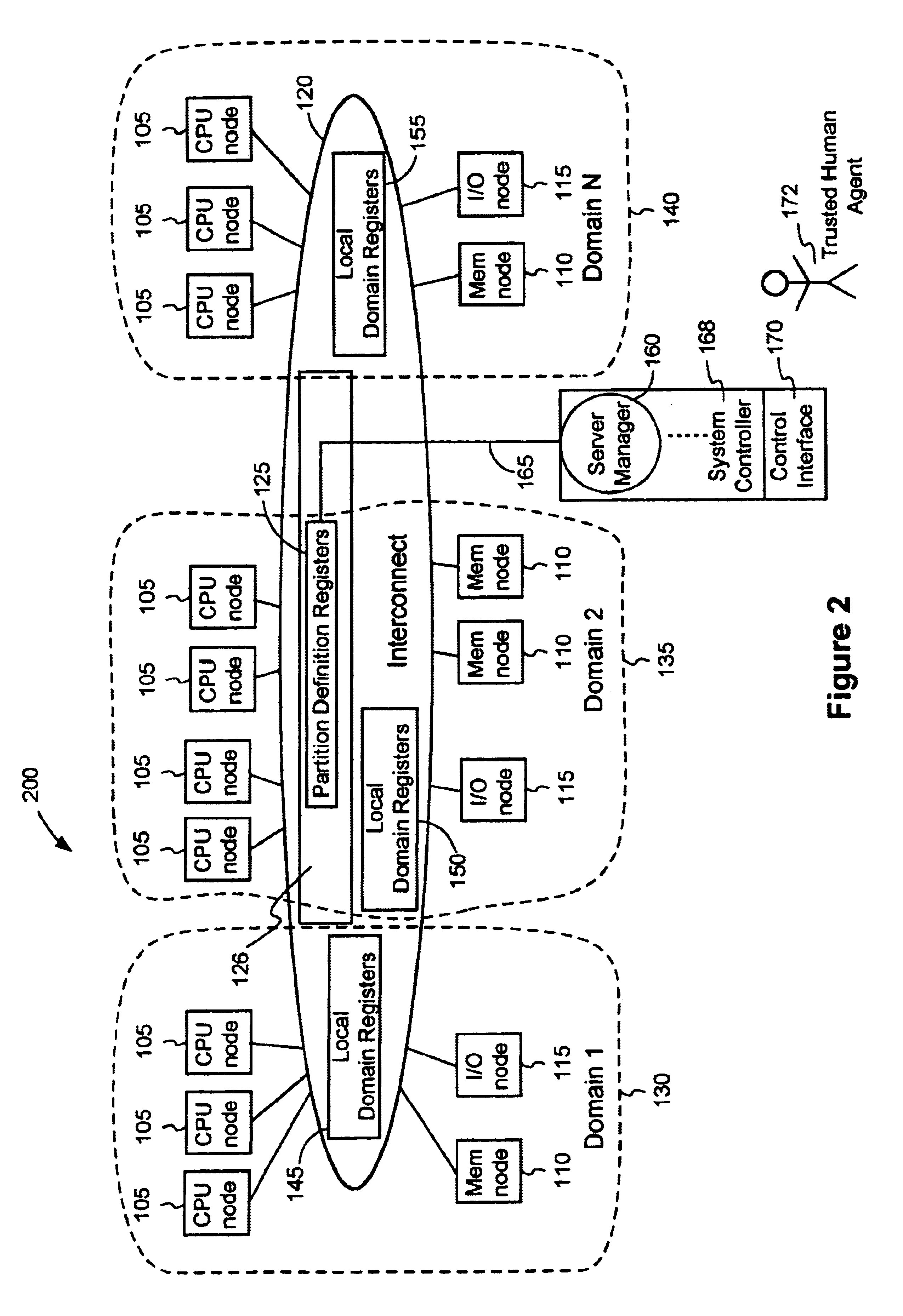
[0014]The present invention includes a system and a method for partitioning a multimode computer system into domains. FIG. (FIG.) 2 is a block diagram of one embodiment of an overall architecture of a multi-node network computer system 200 in accordance with the present invention. In accordance with the present invention, there is provided a multi-node computer system that includes a plurality of central processing unit (CPU) nodes 105, memory nodes 110, and input / output (I / O) nodes 115 coupled to a system interconnect 120. Each node may be implemented on a separate computer chip, computer board, or stand-alone unit. The system interconnect 120 may be, for example, a global interconnect, or include a router. Examples of applications of system 200 include server applications, e.g., system 200 may be a server.

[0015]In one embodiment, a domain configuration unit 126 includes domain configuration registers 125 and routing table registers (not shown in FIG. 2). Domain configuration regis...


PUM


Abstract

A domain partitioning system for a multi-node computer system is disclosed. An external server manager is coupled to a domain configuration unit by a dedicated sideband channel. The server manager has write privileges to the domain configuration unit that allows the server manager to control the domain partitioning and the routing tables. None of the domains of the computer system are permitted write access to the domain configuration unit. In one embodiment, the domain configuration unit is a set of domain partition registers and routing table registers coupled to a system interconnect.

Description

BACKGROUND OF THE INVENTION[0001]1. Field of the Invention[0002]The present invention relates generally to partitioning of a computer system into domains, and more particularly programming the domain configuration registers of a multi-node computer system into domains[0003]2. Description of Background Art[0004]Multi-node computer networks are often partitioned into domains, with each domain functioning as an independent machine with its own address space. An operating system runs separately on each domain. Partitioning permits the resources of a computer network to be efficiently allocated to different tasks, to provide flexibility in the use of a computer system, and to provide isolation between computer resources to limit the effects of hardware or software faults in one part of the network from interfering with the operation of the entire system.[0005]FIG. 1 shows an illustration of a multimode computer system including central processing unit (CPU) nodes 105, memory nodes 110, a...

Claims


Application Information

Patent Timeline
IPC IPC(8): H04L12/24G06F9/50G06F15/177
CPCH04L41/0803H04L41/082H04L41/12
Inventor MASUYAMA, KAZUNORICONWAY, PATRICK N.OI, HITOSHIFARRELL, JEREMYMIRYALA, SUDHEERNISHIMURA, YUKIOMURTHY, PRABHU
Owner FUJITSU LTD
Why Eureka
Try Eureka