Organic laser cavity device having incoherent light as a pumping source

a laser cavity and incoherent light technology, applied in the direction of laser details, excitation process/apparatus, active medium materials, etc., can solve the problems of generating residual electrical emissions, complex current laser system, affecting the effect of laser performance,

Inactive Publication Date: 2005-11-08
EASTMAN KODAK CO
View PDF10 Cites 11 Cited by
  • Summary
  • Abstract
  • Description
  • Claims
  • Application Information

AI Technical Summary

Benefits of technology

[0012]The advantages of the invention are the capability of producing a laser emission without residual electromagnetic emissions, high metal content components, batteries and other electronic power sources, and electronic circuits and components. Other advantages include long duration laser emissions, long inactive storage capacity, robust physical configurations, few required components, variable physical configurations, and variable laser emission configurations. In addition, the ability, according to the present invention, to modulate a laser emission with an audio signal such as a human voice.

Problems solved by technology

Current laser systems require complex, expensive, and fragile electronic circuits, components, and batteries, or other electronic power sources.
Metals are required in the construction of these systems and are susceptible to detection due to this metallic content.
These systems also produce residual electrical emissions that could interfere with other electronic / electrical systems.
A problem with all of these structures is that in order to achieve lasing it was necessary to excite the cavities by optical pumping using another laser source.
This low carrier mobility results in a number of problems.
Devices with low carrier mobilities are typically restricted to using thin layers in order to avoid large voltage drops and ohmic heating.
Undesirable electrical noise can be emitted from LEDs and require an external power supply, along with electronic components / circuitry to operate.
Damage to these LEDs and supporting circuitry can occur from external electromagnetic emissions.

Method used


Image

  • Organic laser cavity device having incoherent light as a pumping source
  • Organic laser cavity device having incoherent light as a pumping source
  • Organic laser cavity device having incoherent light as a pumping source

Examples


Embodiment Construction

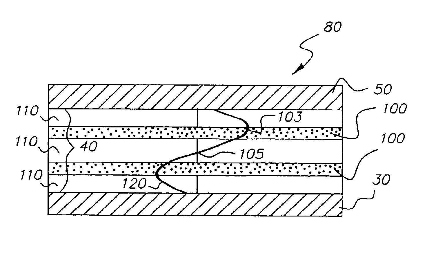
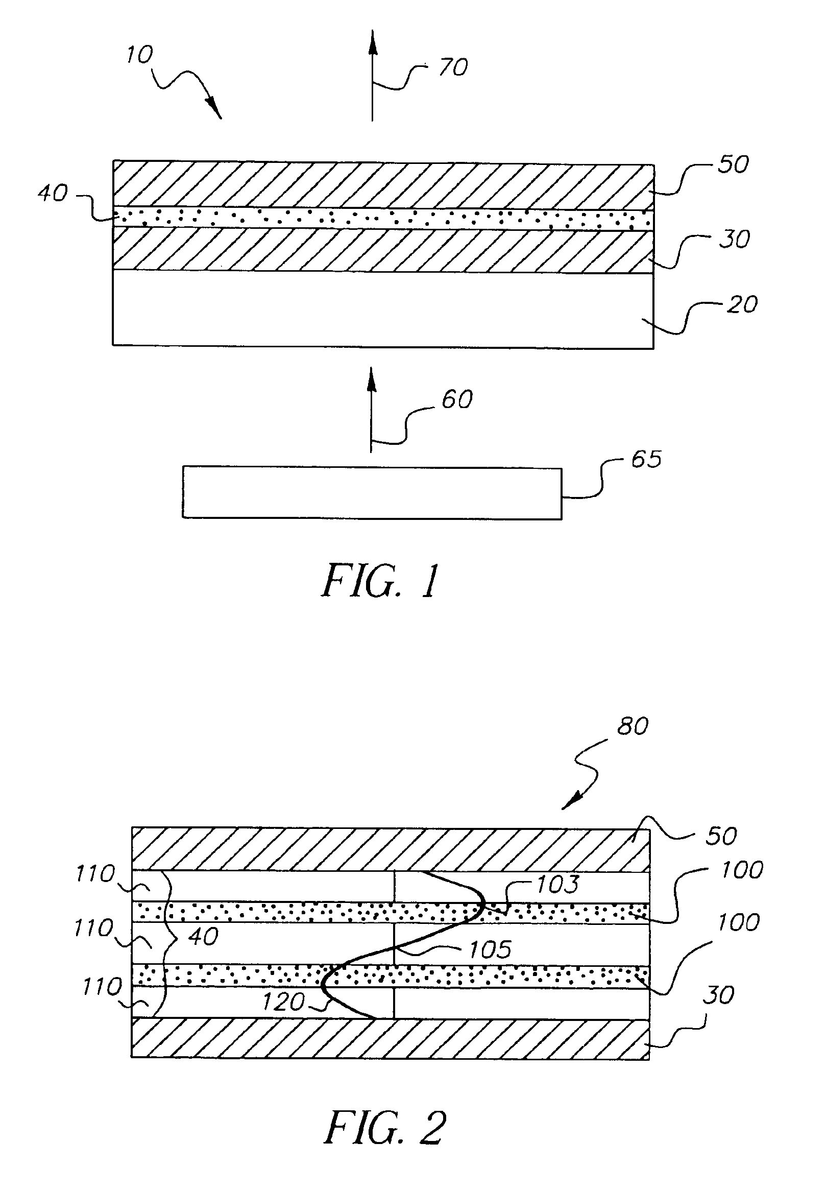
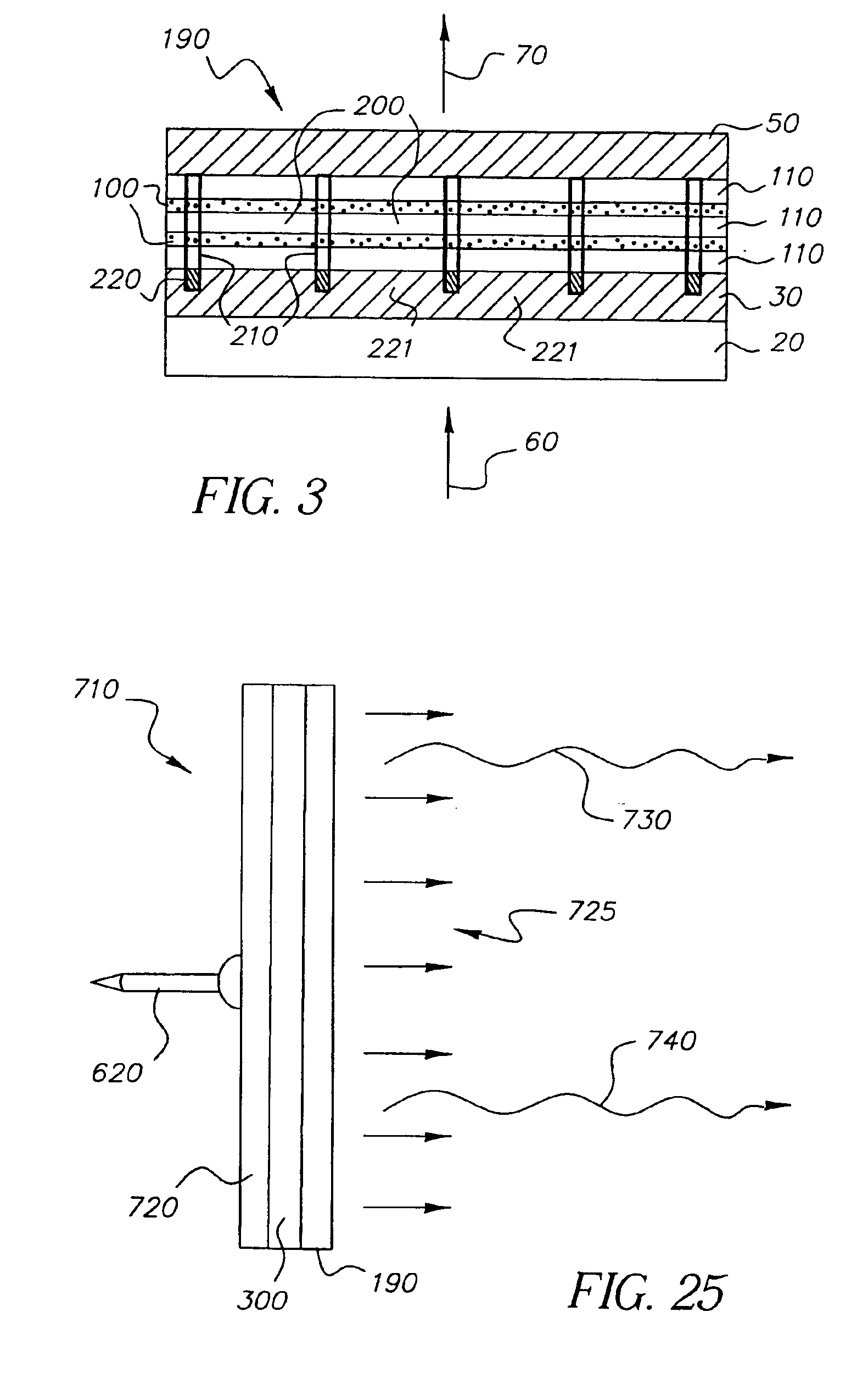
[0054]A VCSEL-based microcavity laser satisfies the criterion of low lasing threshold. Using VCSEL-based organic laser cavities should enable optically pumped power density thresholds below 5 W / cm2. As a result, practical organic laser devices can be driven by optically pumping with a variety of readily available, incoherent light sources, such as self-contained photon sources. Herein, self-contained photon sources are photon sources wherein the energy source for emission of light are chemical, radiological, and biological reactions directly producing photons. These self-contained photon sources do not require external electrical connections for their operation.

[0055]Several types of self-contained photon producing processes that do not have electrical noise characteristics can include; incandescence, luminescence, bioluminescence, thermoluminescence, fluorescence, phosphorescence, and radioluminescence photon processes.

[0056]Radioluminescence (RL) is the generation of photons by a ...


PUM


Abstract

An organic laser cavity device, that includes: a first dielectric stack for receiving and transmitting pumped beam light and being reflective to laser light over a predetermined range of wavelengths and having a substantially low threshold for optical excitation; an organic active region for receiving the transmitted pumped beam light and laser light from the first dielectric stack, and emits the laser light; a second dielectric stack for reflecting the transmitted pumped beam light and the laser light from the organic active region back into the organic active region, wherein a combination of the first and second dielectric stacks and the organic active region outputs the laser light; and an external self-contained photon source of the pumped beam light cooperating with the organic laser cavity for optical excitation at the substantially low threshold.

Description

CROSS-REFERENCE TO RELATED APPLICATIONS[0001]Reference is made to commonly assigned U.S. patent application Device Apparatus for Driving Vertical Laser Cavity” by Keith B. Kahen et al.; commonly assigned U.S. patent application Ser. No. 10 / 066,936 filed Feb. 4, 2002 titled “Organic Vertical Cavity Lasing Devices Containing Periodic Gain Regions” by Keith B. Kahen et al.; and commonly assigned U.S. patent application Ser. No. 10 / 066,829 filed Feb. 4, 2002 titled “Organic Vertical Cavity Phase-Locked Laser Array Device” by Keith B. Kahen, the disclosures of which are incorporated herein by reference.FIELD OF THE INVENTION[0002]The invention relates generally to the field of vertical cavity organic lasers, and in particular to using non-conventional pump beam photon sources to produce laser emissions. More specifically, the invention relates to using self-contained photon sources wherein the energy source for producing photons are chemical, radiological, and biological reactions.BACKGR...

Claims


Application Information

Patent Timeline
Patent Type & Authority Patents(United States)
IPC IPC(8): H01S3/13H01S3/14H01S3/0955H01S3/0957H01S5/30H01S3/091H01S3/09H01S3/0915H01S3/213H01S3/20H01S5/00H01S3/095H01S5/183H01S5/36
CPCH01S5/022H01S5/18383H01S5/36H01S3/095H01S5/041H01S5/18369
Inventor MANICO, JOSEPH A.SPOONHOWER, JOHN P.PATTON, DAVID L.COVANNON, EDWARD
Owner EASTMAN KODAK CO
Why Eureka
Try Eureka