Tie-down for a beach umbrella

a beach umbrella and tie-down technology, applied in the field of tie-down systems, to achieve the effect of convenient compacting and folding

Inactive Publication Date: 2005-11-15
NABER MICHAEL JOHN
View PDF27 Cites 35 Cited by
  • Summary
  • Abstract
  • Description
  • Claims
  • Application Information

AI Technical Summary

Benefits of technology

[0020]A beach umbrella provides an elongated support shaft having a pointed distal end inserted into a soft surface, and a proximal folding canopy positioned below an upper terminal end of the support shaft. The folding canopy provides a fabric panel stretched over a plurality of ribs engaged with the support shaft and extending radially from it to form a convex upfacing surface. A flexible strap has an adjustable loop fitted over and tightened about the upper terminal end of the support shaft and an opposing eyelet engaged with the terminal end of one of the ribs. Adjustment is possible to secure the line between the end of the rib and the upper end of the support shaft. A securing line is fixed at a distal end of the strap and to a stake driven into the soft surface so the line forms a downwardly divergent angle with the support shaft. The flexible strap lies in contact with the external surface of the fabric panel. Because the strap and line and other hardware items of the invention are easily compacted and folded, one may carry them in a small pouch or sack for convenience.

Problems solved by technology

The prior art teaches a beach umbrella safety system, tent securing lines, a sand anchoring system, dressing booth anchorage, umbrella net securement, folded umbrella securement, tie-downs for an umbrella, magnetic fastening of an umbrella, and decorative securement for a parasol, but does not teach a beach umbrella strap and anchor line adapted for engagement with a beach umbrella in a manner to hold the umbrella in a fixed position against a wind force.

Method used


Image

  • Tie-down for a beach umbrella
  • Tie-down for a beach umbrella

Examples


Embodiment Construction

[0028]The above described drawing figures illustrate the invention in at least one of its preferred embodiments, which is further defined in detail in the following description.

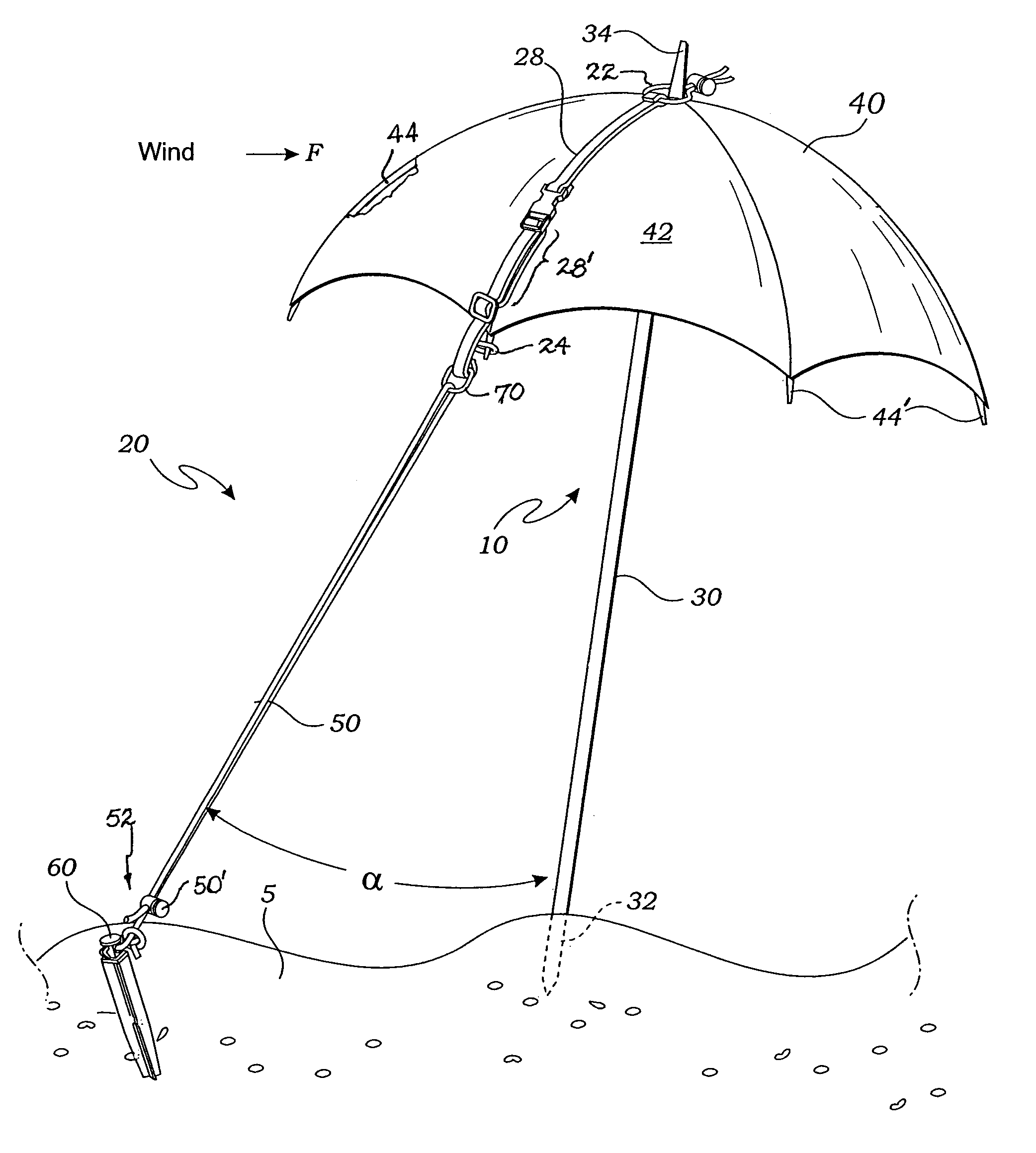
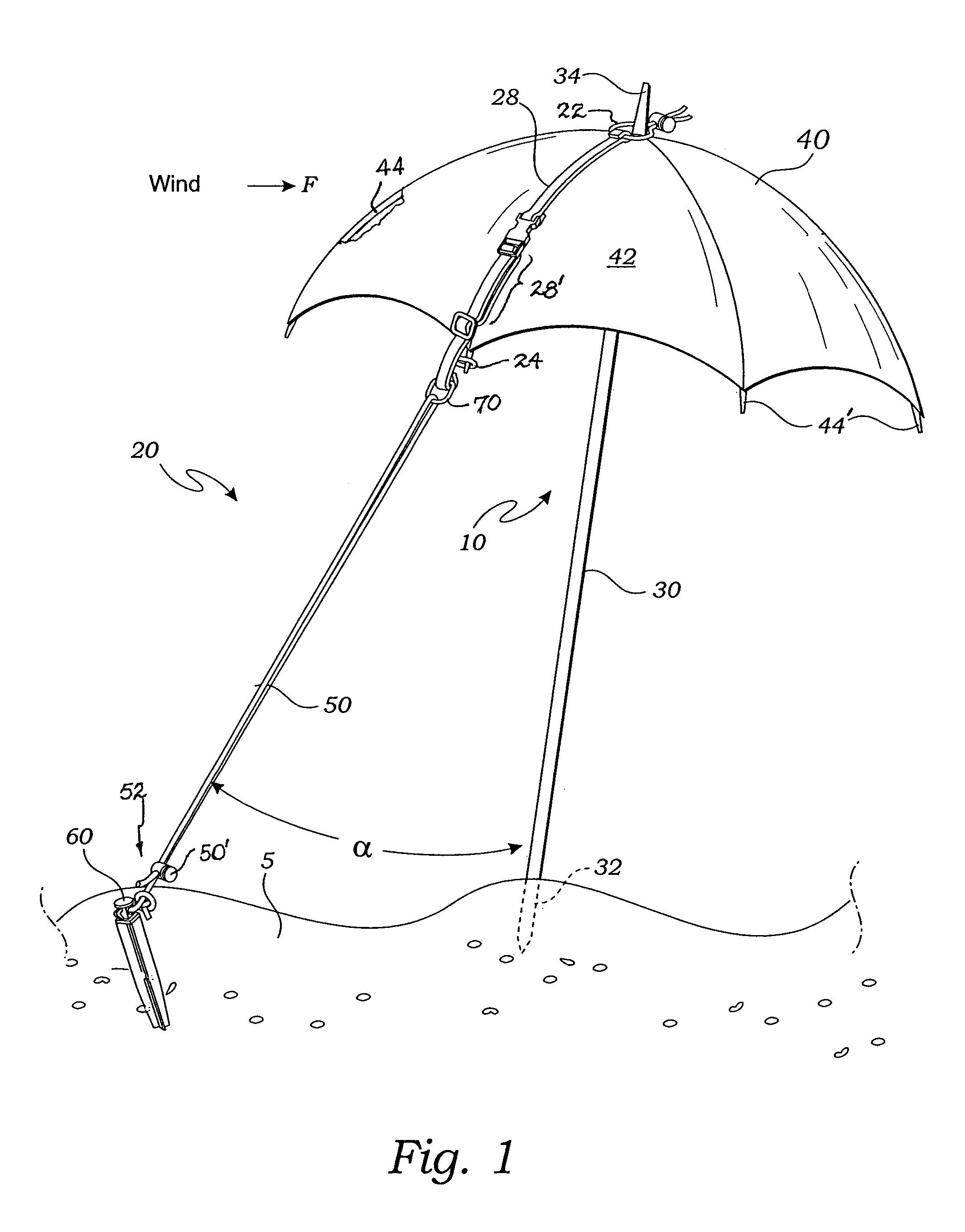
[0029]The present invention is a means for securing an umbrella against a wind force; see FIG. 1. The invention is a combination of a folding beach umbrella 10 of any ordinary type, and an umbrella securing apparatus 20. The beach umbrella 10 provides an elongated support shaft 30 typically of wood or metal or other structural material. This support shaft 30 preferably has a pointed distal end 32 so that it may be more easily inserted or driven into a soft supporting surface 5 such as beach sand or garden soil, for instance for holding the umbrella in an upright attitude as shown. The umbrella 10 has a folding canopy 40 positioned near an upper end 34 of the support shaft 30. This is clearly shown in FIG. 1. The folding canopy 40 provides a fabric panel 42 stretched over a plurality of flexible metal ribs 44 ...


PUM


Abstract

A beach umbrella provides an elongated support shaft having a pointed distal end inserted into a soft surface, and a proximal folding canopy positioned below an upper terminal end of the support shaft. The folding canopy provides a fabric panel stretched over a plurality of ribs engaged with the support shaft and extending radially from it to form a downwardly convex external surface. A flexible strap is attached over the upper terminal end of the support shaft and an opposing eyelet engaged with the tip of one of the ribs of the umbrella. A securing line is fixed at a distal end to a stake driven into the surface so the line forms a downwardly divergent angle with the support shaft. The flexible strap lies in contact with the external surface of the fabric panel and is joined at its upper end with the strap. Strap and line are arranged to point upwind to counter wind forces so that the umbrella cannot be blown over.

Description

RELATED APPLICATIONS[0001]This is a continuation-in-part application of a prior filed and currently application having Ser. No. 10 / 330,524 and file date of Dec. 26, 2002 now abandoned.INCORPORATION BY REFERENCE[0002]Applicant(s) hereby incorporate herein by reference, any and all U.S. patents, U.S. patent applications, and other documents and printed matter cited or referred to in this application.BACKGROUND OF THE INVENTION[0003]1. Field of the Invention[0004]This invention relates generally to restraint systems; particularly of the guy-wire type, and more particularly to a restraint for use in securing a beach umbrella in place.[0005]2. Description of Related Art[0006]The following art defines the present state of this field:[0007]Maul et al., U.S. Pat. No. 245,580 describes a parasol attachment consisting of the two strands or cords connected to the parasol, and combined with the slide, through which the cords or strands are passed, and in which they are crossed.[0008]Barcus, U.S...

Claims


Application Information

Patent Timeline
Patent Type & Authority Patents(United States)
IPC IPC(8): A45B25/00
CPCA45B25/00A45B2023/0012A45B2025/003
Inventor NABER, MICHAEL JOHN
Owner NABER MICHAEL JOHN
Why Eureka
Try Eureka