Nacelle chine installation for drag reduction

a technology of nacelle and chine, which is applied in the direction of aircraft power plant components, air-flow influencers, transportation and packaging, etc., can solve the problems of increasing the noise of the airport, not wanting to accept the consequences of providing those services, and people who have moved toward the airport experience some of the noise associated with air travel, so as to reduce the drag of the aircraft wing assembly, improve the climb gradient of the aircraft, and reduce the drag of the wing

Inactive Publication Date: 2005-11-15
THE BOEING CO
View PDF10 Cites 19 Cited by
  • Summary
  • Abstract
  • Description
  • Claims
  • Application Information

AI Technical Summary

Benefits of technology

[0009]Embodiments of the present invention provide an apparatus and a method for reducing drag of an aircraft wing assembly. A chine or vortex control device is disposed on an outer surface of an engine nacelle. Reduction of drag over the wing and nacelle assembly improves the climb gradient of the aircraft, thereby allowing the aircraft to operate so as to reduce noise disturbances caused by the aircraft. Position and shape of the nacelle chine can be optimized to reduce drag for a variety of aircraft wing and nacelle assemblies. For example, the position and shape can be optimized for aircraft with and without leading edge high lift devices and other factors. In addition, while reducing drag, placement and shape of the chine can also be adjusted to reduce drag and increase the lift coefficient.
[0010]More particularly, embodiments of the present invention provide an apparatus and a method for reducing drag of an aircraft wing assembly where the aircraft wing assembly includes a wing and an engine nacelle mounted to the wing. Embodiments of the present invention include a nacelle chine mounted on an outboard side of the engine nacelle, the nacelle chine being configured to reduce drag by redirecting at least a portion of fluid striking a forward end of the aircraft wing assembly such that a vortex is formed over the forward end of the aircraft wing assembly. Embodiments of the invention also include a mounting base configured to be secured to an outer surface of the engine nacelle at a mounting position along an outer surface of the engine nacelle. Embodiments of the invention also include a wing assembly incorporating the chine and an aircraft incorporating the chine.

Problems solved by technology

However, while the population wants sufficient services, they may not want to accept consequences which attend provision of those services.
Ultimately, people who have moved toward the airport experience some of the noise associated with air travel.
Increased airport noise presents problems.
However, nearby residents did not want to the additional noise that would result from the air traffic taking off from and landing on that new runway.
Travelers who flew into and out of Charlotte experienced tremendous delays as a result.
Practically, there is no way to prevent population growth around an airport.
As previously described, drag reduces the climb gradient and, thus, results in added noise around airports.

Method used


Image

  • Nacelle chine installation for drag reduction
  • Nacelle chine installation for drag reduction
  • Nacelle chine installation for drag reduction

Examples


Embodiment Construction

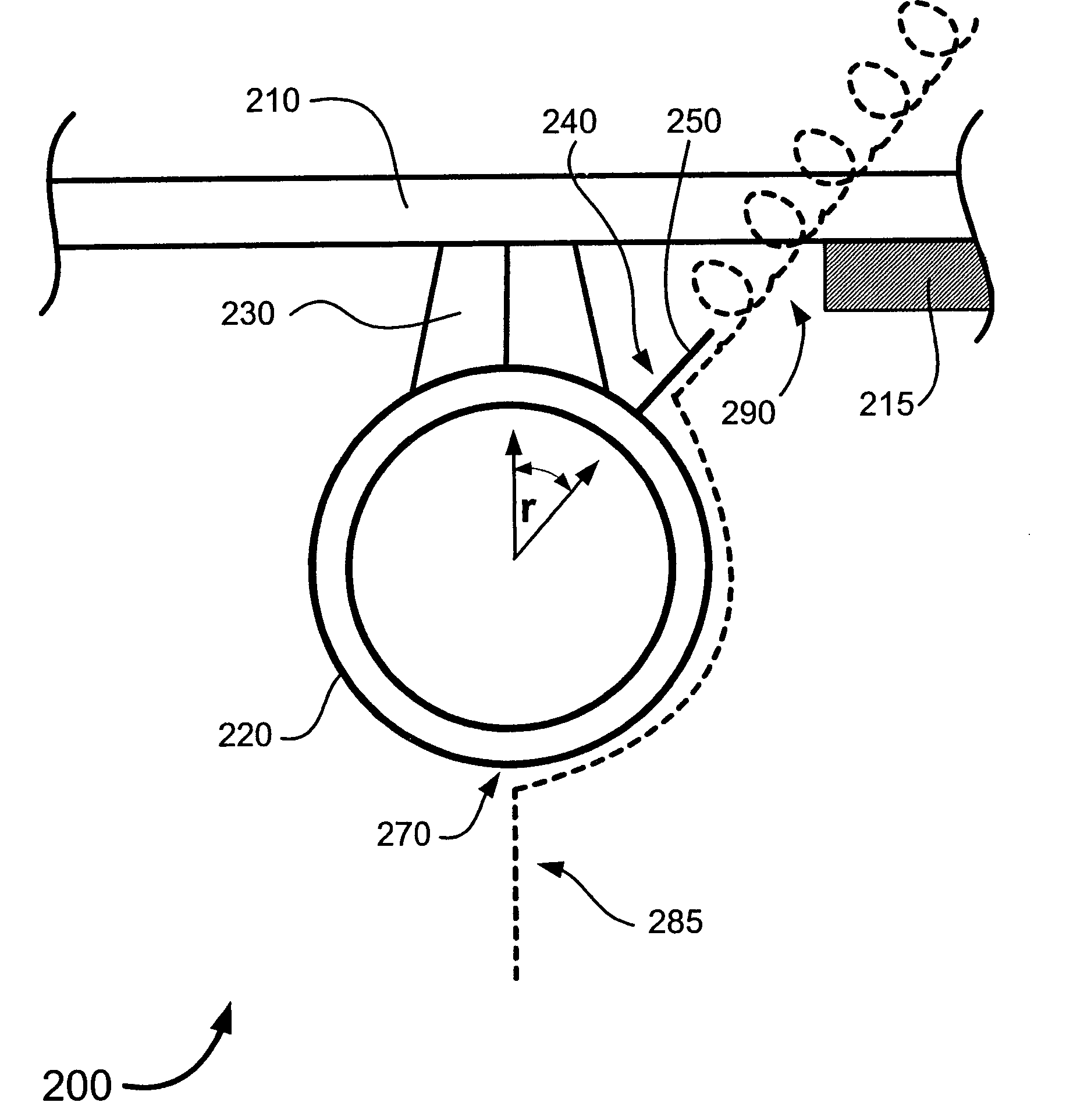
[0020]By way of overview, embodiments of the present invention provide an apparatus and a method for reducing drag of an aircraft wing assembly in operational angle of attack portions of flight where the aircraft wing assembly includes a wing and an engine nacelle mounted to the wing. Embodiments of the present invention include a nacelle chine mounted on an outboard side of the engine nacelle, and the nacelle chine is configured to reduce drag by redirecting at least a portion of fluid striking a forward end of the aircraft wing assembly such that a vortex is formed over the forward end of the aircraft wing assembly. Embodiments of the invention also include a mounting base configured to be secured to an outer surface of the engine nacelle at a mounting position along an outer surface of the engine nacelle. Embodiments of the invention also include a wing assembly incorporating the chine and an aircraft incorporating the chine.

[0021]FIG. 2 shows a perspective view of a wing assembl...


PUM


Abstract

An apparatus and a method for reducing drag over an aircraft wing assembly in operational angle of attack situations are disclosed. The aircraft wing assembly includes a wing and an engine nacelle mounted to the wing. A nacelle chine is mounted on an outboard side of the engine nacelle, and the nacelle chine is configured to reduce drag by redirecting at least a portion of fluid striking a forward end of the aircraft wing assembly such that a vortex is formed over the forward end of the aircraft wing assembly. The chine is coupled to a mounting base configured to be secured to an outer surface of the engine nacelle at a mounting position along an outer surface of the engine nacelle.

Description

FIELD OF THE INVENTION[0001]This invention relates generally to aerodynamics of aircraft and, more specifically, to aircraft wake controls.BACKGROUND OF THE INVENTION[0002]Air travel has continued to grow in popularity. At the same time, air carriers are serving an ever-growing population. However, while the population wants sufficient services, they may not want to accept consequences which attend provision of those services. To take a common example, as cities grow, suburbs and population centers expand toward the direction of what used to be a remotely located airport. At the same time, to serve the growing population, more flights might be added. Ultimately, people who have moved toward the airport experience some of the noise associated with air travel.[0003]Increased airport noise presents problems. For example, in the late 1980s, the airport serving the city of Charlotte, N.C., added runway capacity to support additional air traffic needed to support the burgeoning community....

Claims


Application Information

Patent Timeline
Patent Type & Authority Patents(United States)
IPC IPC(8): B64D29/02B64D29/00B64C7/00B64C7/02
CPCB64C7/02B64D29/02
Inventor KONINGS, CHRISTOPHER A.
Owner THE BOEING CO
Why Eureka
Try Eureka