Percutaneous catheter and guidewire having filter and medical device deployment capabilities

a technology of percutaneous catheter and guidewire, which is applied in the field of plaque deposits and occlusions, can solve the problems of serious complications, permanent injuries or even death of patients, damage to patients,

Inactive Publication Date: 2005-11-15
BOSTON SCI SCIMED INC
View PDF330 Cites 263 Cited by
  • Summary
  • Abstract
  • Description
  • Claims
  • Application Information

AI Technical Summary

Benefits of technology

[0010]The present invention provides an apparatus and method for preventing embolic material from escaping a site of intervention within the aorta, the carotid arteries, and other arteries generally, thereafter causing damage to vital organs, such as the brain. More particularly, the present invention involves an apparatus and method for introducing a stent into a region of a major blood vessel within the human body having plaque deposits, such as the ascending aorta, the descending aorta, aortic arch, common carotid artery, external and internal carotid arteries, brachiocephalic trunk, middle cerebral artery, anterior cerebral artery, posterior cerebral artery, vertebral artery, basilar artery, subclavian artery, brachial artery, axillary artery, iliac artery, renal artery, femoral artery, popliteal artery, celiac artery, superior mesenteric artery, inferior mesenteric artery, anterior tibial artery, and posterior tibial artery, thereby opening occlusions and / or preventing embolic material from breaking free within the blood vessel.

Problems solved by technology

Plaque material may be inadvertently dislodged during angioplasty, and this material is then free to travel downstream, possibly lodging within another portion of the blood vessel or possibly reaching a vital organ, causing damage to the patient.
When this material travels downstream, it can cause serious complications.
For example loose embolic material released within the ascending aorta, the aortic arch, or the carotid arteries may travel downstream to the brain, possibly causing stroke, which can lead to permanent injuries or even death of the patient.

Method used


Image

  • Percutaneous catheter and guidewire having filter and medical device deployment capabilities
  • Percutaneous catheter and guidewire having filter and medical device deployment capabilities
  • Percutaneous catheter and guidewire having filter and medical device deployment capabilities

Examples


Embodiment Construction

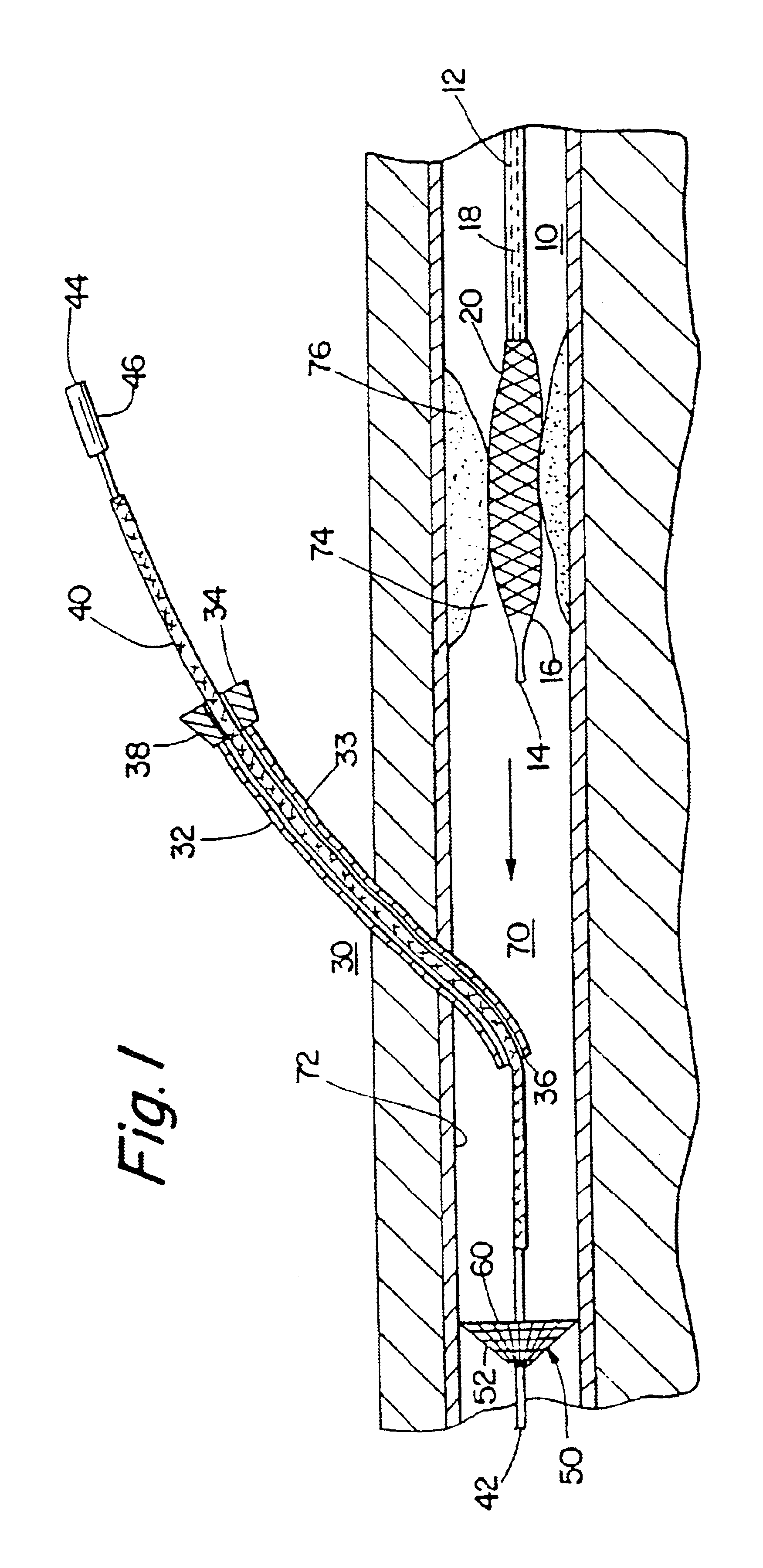
[0062]Turning to FIG. 1, a first embodiment of the present invention is shown, namely a stent catheter 10 and a filter device 30. The stent catheter 10 typically includes a catheter body 12, an inflatable balloon 16, and a stent 20. The catheter body 12 typically comprises a substantially flexible member having a proximal end (not shown) and a distal end 14. The balloon is mounted on a region at or near the distal end 14 of the catheter body 12. An inflation lumen 18 extends longitudinally from a region at or near the proximal end of the catheter body 12 to the balloon 16.

[0063]The stent 20 is introduced over the balloon 16, typically by manually compressing it onto the balloon 16. The stent 20 may comprise a tube, sheet, wire, mesh or spring, although preferably, it is a substantially cylindrical wire mesh sleeve, that is substantially rigid, yet expandable when subjected to radial pressure. Many known stent devices are appropriate for use with the present invention, such as those ...


PUM


Abstract

The invention provides a nested tubing cannula which comprises outer and inner elongate tubular members, both having a proximal end, a distal end, and a lumen therebetween. The inner tubular member is sealed at its distal end and is nested substantially coaxially within the lumen of the outer tubular member, so that the gap between the inner and the outer tubular member defines a second lumen whereas the first lumen is the lumen of the inner tubular member. A tubular sleeve is disposed coaxially between the inner and outer tubular members. A balloon is mounted on a distal region of the outer tubular member and is in communication with the first lumen. The cannula further comprises a port proximal or distal the balloon occluder and is in communication with the second lumen. Methods for making the devices herein are disclosed.

Description

[0001]This application is a continuation of application Ser. No. 09 / 679,911, filed Oct. 5, 2000 now U.S. Pat. No. 6,676,682, which is a continuation of Ser. No. 09 / 421,138, filed Oct. 19, 1999, now U.S. Pat. No. 6,165,200, which in turn is a continuation of application Ser. No. 09 / 287,217, filed Apr. 5, 1999, now U.S. Pat No. 6,027,520, which is a continuation of application Ser. No. 09 / 022,510, filed Feb. 12, 1998, now U.S. Pat. No. 5,910,154, which is a continuation of application Ser. No. 08 / 852,867, filed May 8, 1997, now U.S. Pat. No. 5,911,734. Each of the above applications is hereby expressly and fully incorporated herein by reference.FIELD OF THE INVENTION[0002]The present invention relates generally to treating plaque deposits and occlusions within major blood vessels, more particularly to an apparatus and method for preventing detachment of mobile aortic plaque within the ascending aorta, the aortic arch, or the carotid arteries, and to an apparatus and method for providi...

Claims


Application Information

Patent Timeline
Patent Type & Authority Patents(United States)
IPC IPC(8): A61F2/01A61F2/06A61F2/02A61F2/82
CPCA61F2/01A61F2/013A61B2017/320716A61F2/82A61F2/95A61F2002/011A61F2250/0003A61F2002/018A61F2230/0006A61F2230/005A61F2230/0067A61F2230/0071A61F2230/0076A61F2230/008A61F2/011
Inventor TSUGITA, ROSS S.MAAHS, TRACY D.JANG, YUE-TEH
Owner BOSTON SCI SCIMED INC
Why Eureka
Try Eureka