
Planar sensor element

Inactive Publication Date: 2005-11-15
ROBERT BOSCH GMBH
View PDF9 Cites 6 Cited by
  • Summary
  • Abstract
  • Description
  • Claims
  • Application Information

AI Technical Summary

Benefits of technology

[0004]Thus, a resistance of the sensor element to temperature variations and thermal shock is improved. Furthermore, the efficiency of the heating element is enhanced.

Problems solved by technology

The non-homogeneous distribution of the heating power results in increased heat shock sensitivity of the planar sensor element when the temperature varies.

Method used


Image

  • Planar sensor element
  • Planar sensor element

Examples


Embodiment Construction

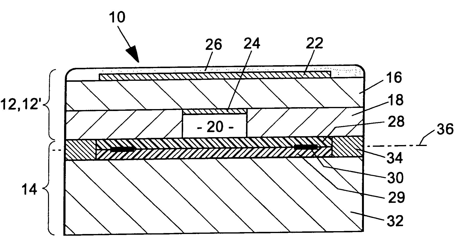
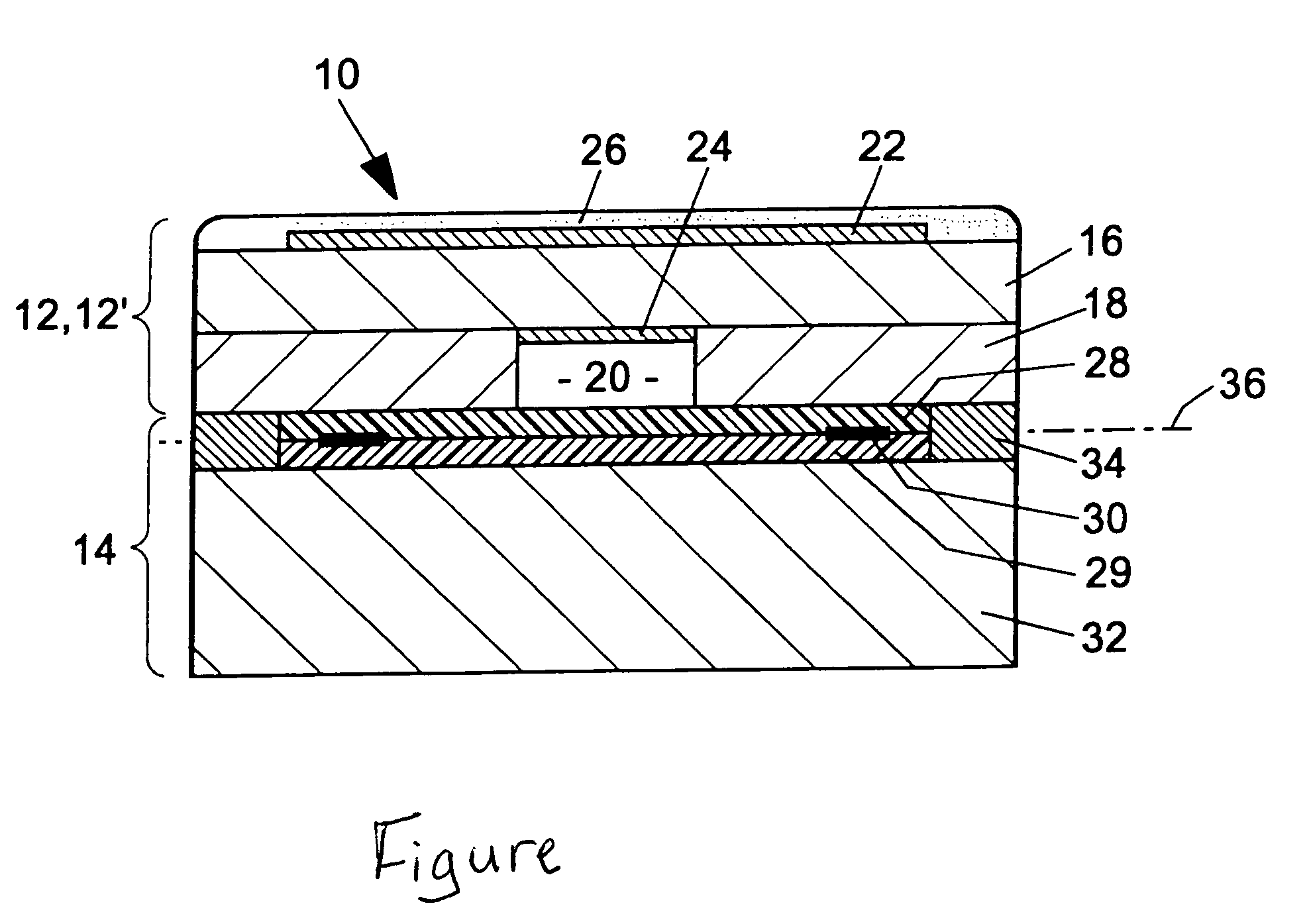
[0007]The FIGURE shows a cross section through an exemplary embodiment of a planar sensor element 10, which may be used, e.g., for determining the oxygen level in exhaust gases of internal combustion engines or combustion systems. The sensor element shown in this embodiment is a lambda-1 sensor (e.g., a Nernst sensor). The design and function of such a sensor are generally known.

[0008]Sensor element 10 has, when unsintered, an elongated, plate-shaped design, which contains a plurality of layers arranged one on top of the other in a layer structure. The layers, when unsintered (green), are basically formed by oxygen ion-conducting solid electrolyte foils.

[0009]In this embodiment according to the present invention, sensor element 10 has an electrochemical measuring cell 12 and a heating element 14. Measuring cell 12 has a function layer-side layer structure 12′ with a first foil 16 and a second foil 18. A reference channel 20 is integrated in second foil 18. A measuring electrode 22 i...


PUM


Abstract

A planar sensor element for determining gas components, which includes a layer structure with a heating element integrated therein with a layer-shaped heating conductor. The heating conductor is arranged in a layer plane of the layer structure so that an at least approximately homogeneous distribution of the heating power of the heating element over the cross-section of the layer structure is obtained.

Description

FIELD OF THE INVENTION[0001]The present invention relates to a planar sensor element for determining gas components, in particular for determining the oxygen level in internal combustion engine exhaust gases.BACKGROUND INFORMATION[0002]A conventional sensor element is described in, for example, German Patent Application No. 42 31 966 (corresponding to U.S. Pat. No. 5,529,677), which is made of a composite of individual foils arranged in consecutively superimposed layers. Function layers such as electrodes, printed conductors and an electric resistance heating element are arranged between the individual foils. The function layers and the heating element are printed onto the unsintered (green) foils using screen printing, for example. Then, the foils are placed one on top of the other, laminated and subsequently sintered. In the planar sensor element of this type, the resistance heating element is arranged in one of the layers between an external cover foil and an adjacent layer struc...

Claims


Application Information

Patent Timeline
IPC IPC(8): G01N27/407G01N27/409
CPCG01N27/4071
Inventor SCHNEIDER, GERHARDNEUMANN, HARALD
Owner ROBERT BOSCH GMBH
Learn More