
Non-aqueous electrolyte secondary battery

a non-aqueous electrolyte, secondary battery technology, applied in secondary cells, battery servicing/maintenance, sustainable manufacturing/processing, etc., can solve the disadvantage of lowering the high-rate performance of the non-aqueous electrolyte secondary battery, lowering the resistance against precipitation of li, and suppressing the variation of the resistance of the electrode

Active Publication Date: 2020-10-06
TOYOTA JIDOSHA KK
View PDF8 Cites 0 Cited by
  • Summary
  • Abstract
  • Description
  • Claims
  • Application Information

AI Technical Summary

Benefits of technology

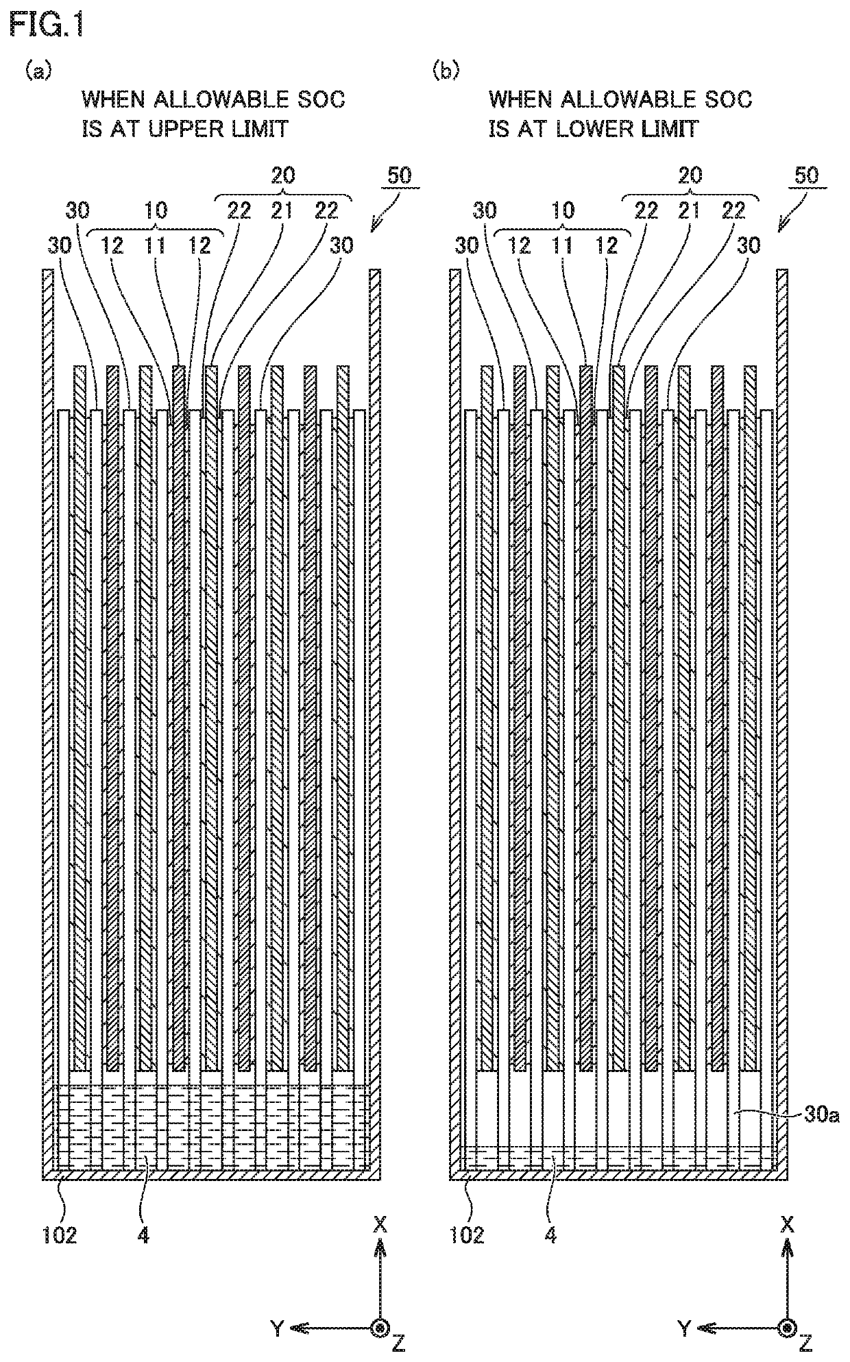
[0006]Therefore, an object of the present disclosure is to provide a non-aqueous electrolyte secondary battery improved in resistance against precipitation of Li by suppression of variation in resistance of an electrode and improved in high-rate performance by suppression of dry-up or change in concentration of salt of an electrolyte solution in an electrode array.
[0008]According to the present disclosure, the projecting portion of the separator is always in contact with the excess portion of the electrolyte solution so that the electrolyte solution can reversibly be returned from the excess portion to the electrode array through the separator. Therefore, dry-up or change in concentration of salt, of the electrolyte solution in the electrode array is suppressed, so that high-rate performance of the non-aqueous electrolyte secondary battery is improved. Since the electrode is not in contact with the excess portion of the electrolyte solution at any time, variation in resistance of the electrode is suppressed. Thus, resistance against precipitation of Li of the non-aqueous electrolyte secondary battery is improved.
[0009][2] In the set-up state, the projecting portion of any of the plurality of separators is in contact with the housing in some embodiments. In this case, dry-up or change in concentration of salt of the electrolyte solution is more reliably suppressed and high-rate performance of the non-aqueous electrolyte secondary battery is improved. This is because, when the projecting portion of the separator is in contact with (an inner wall of a bottom of) the housing in the set-up state, the separator can more reliably be in contact with the excess portion of the electrolyte solution stored at the bottom of the housing.
[0010][3] In some embodiments, the lower limit value of the allowable state of charge is not higher than 20% and the upper limit value of the allowable state of charge is not lower than 80%. In this case, even though the range of the allowable state of charge is wide (the lower limit value of the allowable state of charge is set to 20% and the upper limit value of the allowable state of charge is set to 80%), variation in resistance of the electrode is more reliably suppressed so that resistance against precipitation of Li of the non-aqueous electrolyte secondary battery is improved. Dry-up or change in concentration of salt of the electrolyte solution is suppressed so that high-rate performance of the non-aqueous electrolyte secondary battery is improved.

Problems solved by technology

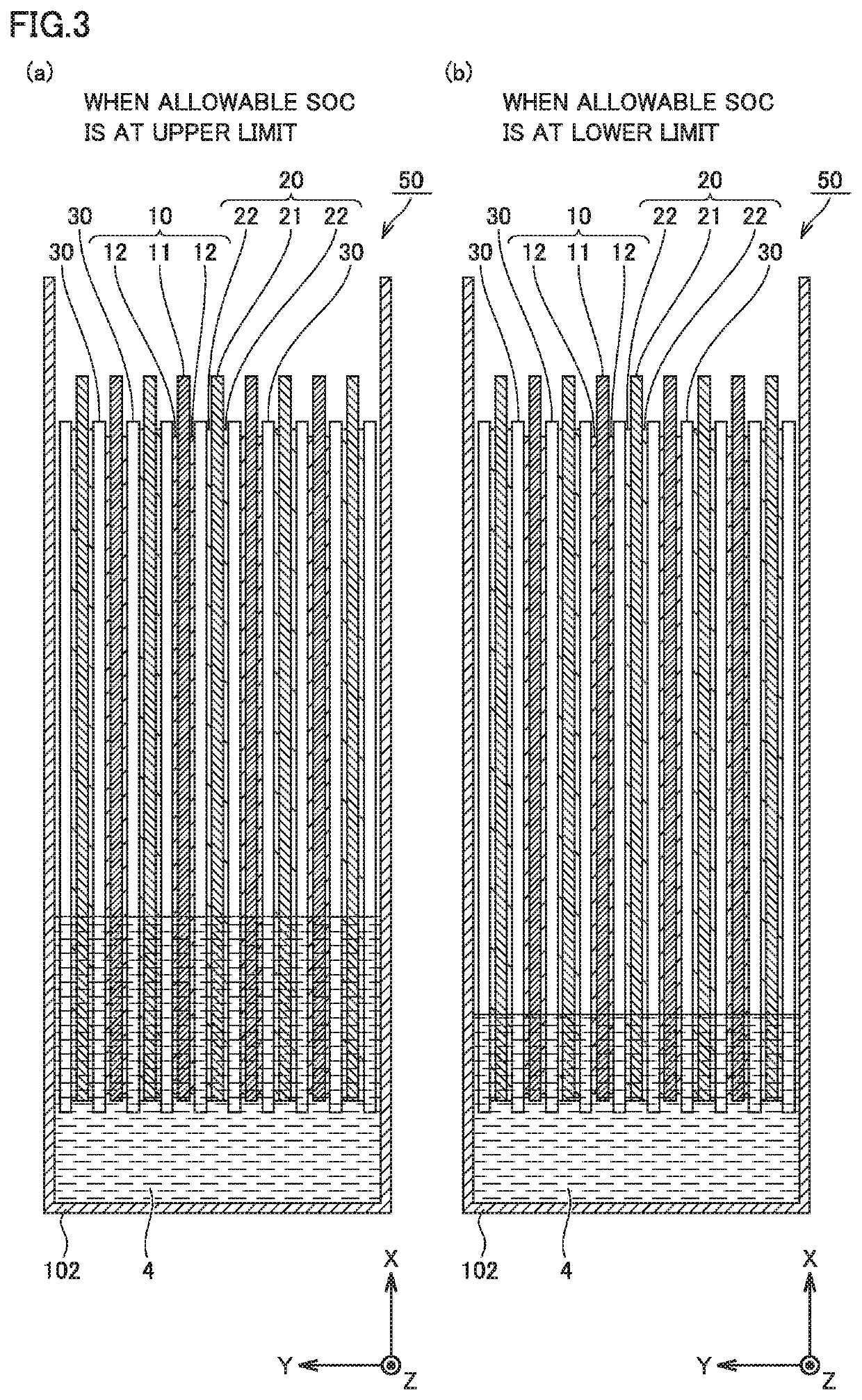
Such variation in resistance leads to tendency of local precipitation of Li at a surface of the electrode (lowering in resistance against precipitation of Li).
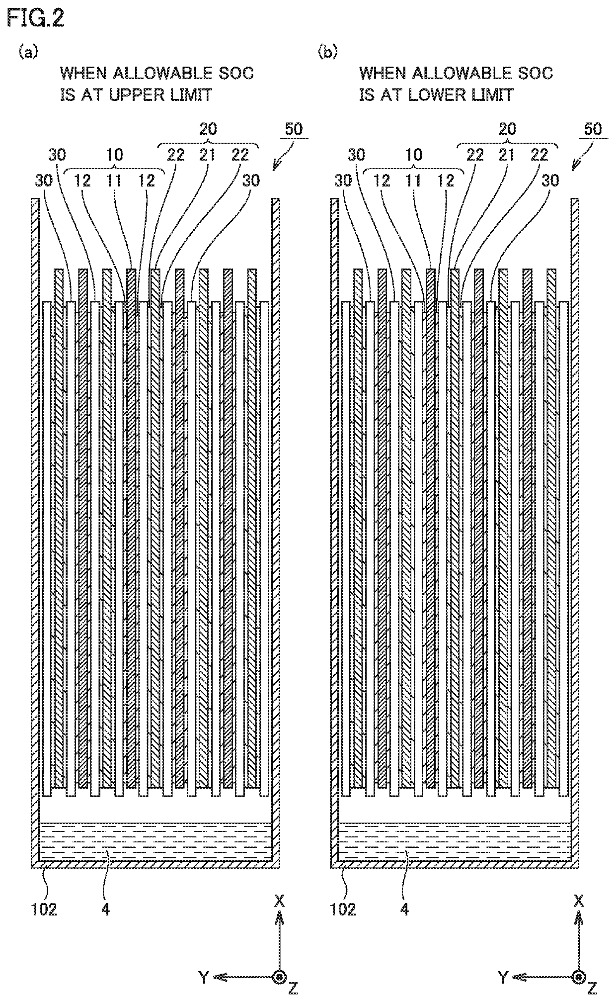
Decrease in amount of the electrolyte solution for avoiding contact with the electrode, however, may lead to a state that the excess portion, of the electrolyte solution is not in contact with an electrode array (see FIG. 2) during charging and discharging at a high rate.
Since the excess portion of the electrolyte solution cannot reversibly be returned to the electrode array in this state, characteristics of the battery deteriorate with dry-up of the electrolyte solution or change in concentration of salt in the electrode array.
Namely, high-rate performance of the non-aqueous electrolyte secondary battery disadvantageously lowers.

Method used


Image

  • Non-aqueous electrolyte secondary battery
  • Non-aqueous electrolyte secondary battery
  • Non-aqueous electrolyte secondary battery

Examples


example 1

[0057]>

[0058]Materials below were prepared.

[0059]Positive electrode active material: LiNi0.5Co0.2Mn0.3O2 (NCM523)

[0060]Conductive material: AB

[0061]Binder: PVDF

[0062]Solvent: N-methylpyrrolidone (NMP)

[0063]Positive electrode current collector: aluminum foil (having a thickness of 15 μm)

[0064]Ninety-six parts by mass of positive electrode active material, 2 parts by mass of conductive material, and 2 parts by mass of binder were mixed in a solvent. A positive electrode composite material paste was thus prepared. A positive electrode composite material layer was formed by applying the positive electrode composite material paste to both surfaces of a positive electrode current collector with a die coater and drying the paste. A positive electrode in which the positive electrode composite material layer was stacked on both of the surfaces of the positive electrode current collector was thus manufactured. The positive electrode was further compressed and punched into a prescribed shape. ...


PUM

PropertyMeasurementUnit
thicknessaaaaaaaaaa
thicknessaaaaaaaaaa
thicknessaaaaaaaaaa

Abstract

A non-aqueous electrolyte secondary battery includes a housing, a stack-type electrode array accommodated in the housing, and an electrolyte solution. The electrolyte solution includes an infiltrated portion infiltrated into the stack-type electrode array and an excess portion other than the infiltrated portion. In a set-up state that the non-aqueous electrolyte secondary battery is arranged such that a direction of stack of the stack-type electrode array is orthogonal to a vertical direction, a lower end of the separator projects below lower ends of the positive electrode and the negative electrode. In the set-up state, within a range of an operating state of charge, a projecting portion of any of the plurality separators is always in contact with the excess portion and the plurality of positive electrodes and the plurality of negative electrodes are not in contact with the excess portion at any time.

Description

CROSS-REFERENCE TO RELATED APPLICATIONS[0001]This nonprovisional application claims priority to Japanese Patent Application No. 2018-008906 filed with the Japan Patent Office on Jan. 23, 2018, the entire contents of which are hereby incorporated by reference.BACKGROUNDField[0002]The present disclosure relates to a non-aqueous electrolyte secondary battery.Description of the Background Art[0003]Japanese Patent Laying-Open No. 2017-098156 describes suppression of occurrence of dry-up of an electrolyte solution (shortage of an amount of an electrolyte solution held by an electrode) in one of a positive electrode and a negative electrode and suppression of increase in, resistance of a battery in repeated charging and discharging at a high rate, by balancing, between the positive electrode and the negative electrode, an amount of the electrolyte solution held therein in a non-aqueous electrolyte secondary battery.SUMMARY[0004]In a conventional non-aqueous electrolyte secondary battery as...

Claims


Application Information

Patent Timeline
Patent Type & Authority Patents(United States)
IPC IPC(8): H01M10/00H01M10/42H01M10/0525H01M10/0585H01M10/04H01M2/04H01M50/147
CPCH01M10/0585H01M10/0525H01M10/0413H01M10/4235H01M2/04H01M2220/20H01M10/058H01M10/0568H01M10/0569H01M2300/0025H01M2300/0028H01M50/147Y02E60/10Y02P70/50H01M10/052
Inventor IGUCHI, HIROKI
Owner TOYOTA JIDOSHA KK
Learn More