High pressure discharge lamp and lamp unit

a high pressure discharge and lamp technology, applied in the manufacture of electric discharge tubes/lamps, cold cathode manufacturing, electrode systems, etc., can solve the problems of inability to achieve practical lamps, inability to increase the voltage of lamps to a necessary level, and current techniques have not succeeded in realizing high pressure discharge lamps having a very high strength against. , to achieve the effect of improving the strength against pressure, preventing small cracks, and easy detachmen

Inactive Publication Date: 2005-11-15
PANASONIC CORP
View PDF45 Cites 8 Cited by
  • Summary
  • Abstract
  • Description
  • Claims
  • Application Information

AI Technical Summary

Benefits of technology

[0050]In a high pressure discharge lamp of the present invention, the sealing portion has a first glass portion extending from a luminous bulb, and a second glass portion provided at least in a portion inside the first glass portion, and the sealing portion has a portion to which a compressive stress is applied. The presence of the portion to which a compressive stress is applied improves the strength against pressure of the high pressure discharge lamp.
[0051]When a metal film made of at least one metal selected from the group consisting of Pt, Ir, Rh, Ru, and Re is formed on a surface of at least a portion of the electrode rod that is buried in at least one of the sealing portions, the wettability between the surface of the electrode rod and the glass of the sealing portion becomes poor. Therefore, in the lamp production process, the two components can be easily detached. As a result, it is possible to prevent small cracks from occurring and to improve the strength against pressure of the lamp further. Also when a coil having at least one metal selected from the group consisting of Pt, Ir, Rh, Ru, and Re on at least its surface is wound around at least a portion of the electrode rod that is buried at least in one of the sealing portions, it is possible to prevent small cracks from occurring and to improve the strength against pressure of the lamp further.
[0052]The present invention can be applied not only to a high pressure mercury lamp, but also other high pressure discharge lamps such as a metal halide lamp and a xenon lamp, and can be applied to a mercury-free metal halide lamp that does not contain mercury. A mercury-free metal halide lamp according to the present invention has a high strength against pressure, so that a rare gas can be enclosed to a high pressure. As a result, the efficiency can be improved in a simple manner, and the operation start properties can be improved. The present invention can be applied not only to a high pressure mercury lamp, but also an incandescent lamp (e.g., halogen incandescent lamp), and can make the possibility of breakage lower than in conventional incandescent lamps.
[0053]According to the present invention, the sealing portion has a first glass portion extending from a luminous bulb, and a second glass portion provided at least in a portion inside the first glass portion, and the sealing portion has a portion to which a compressive stress is applied. Thus, the presence of the portion to which a compressive stress is applied provides a high pressure discharge lamp having an improved strength against pressure.

Problems solved by technology

If the amount of mercury enclosed is insufficient relatively to the lamp power, the lamp voltage cannot be increased to a necessary level, so that the lamp current increases.
As a result, the electrodes are evaporated in a short time, and therefore a practical lamp cannot be achieved.
Current techniques have not succeeded in realizing a high pressure discharge lamp having a very high strength against pressure (e.g., about 30 MPa or more) that can be used in practice.

Method used


Image

  • High pressure discharge lamp and lamp unit
  • High pressure discharge lamp and lamp unit
  • High pressure discharge lamp and lamp unit

Examples


embodiment 1

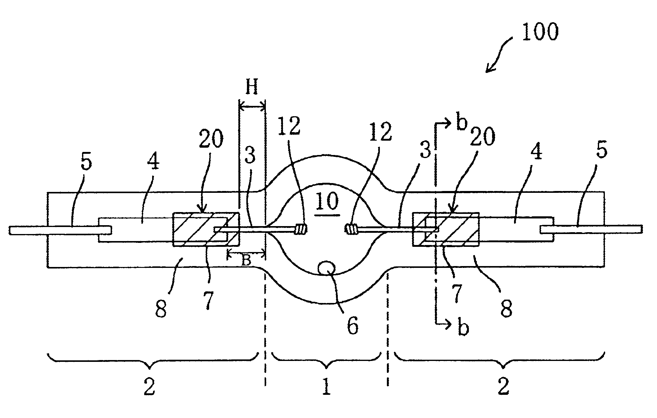
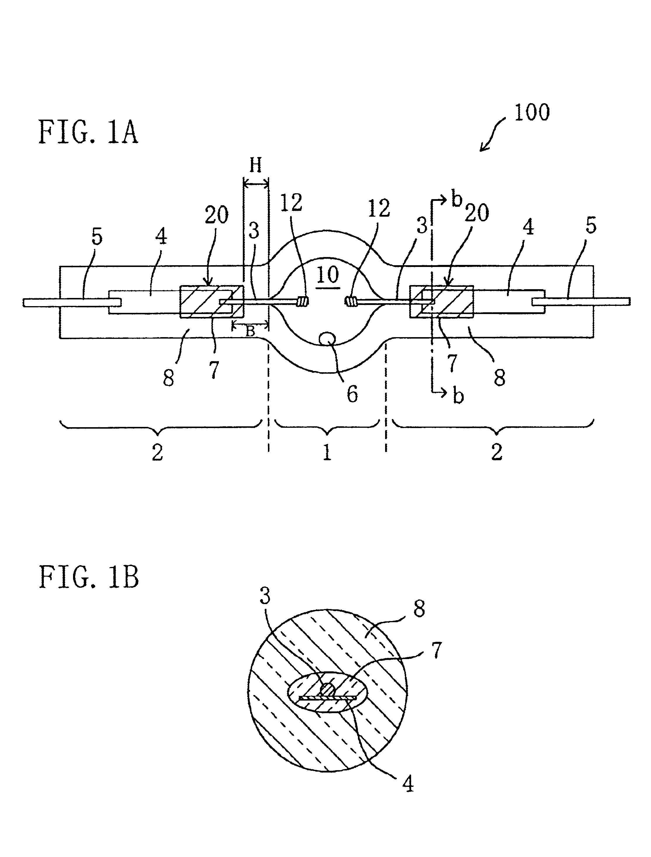
[0096]FIGS. 1A and 1B are schematic views showing the structure of a lamp 100 of this embodiment. The lamp 100 of this embodiment is a high pressure discharge lamp including a luminous bulb 1 and sealing portions 2 extending from the luminous bulb 1. The lamp shown in FIG. 1 is a high pressure mercury lamp. FIG. 1A schematically shows the entire structure of the lamp 100, and FIG. 1B schematically shows the cross-sectional structure of the sealing portion 2 taken along line b—b in FIG. 1A when viewed from the side of the luminous bulb 1.

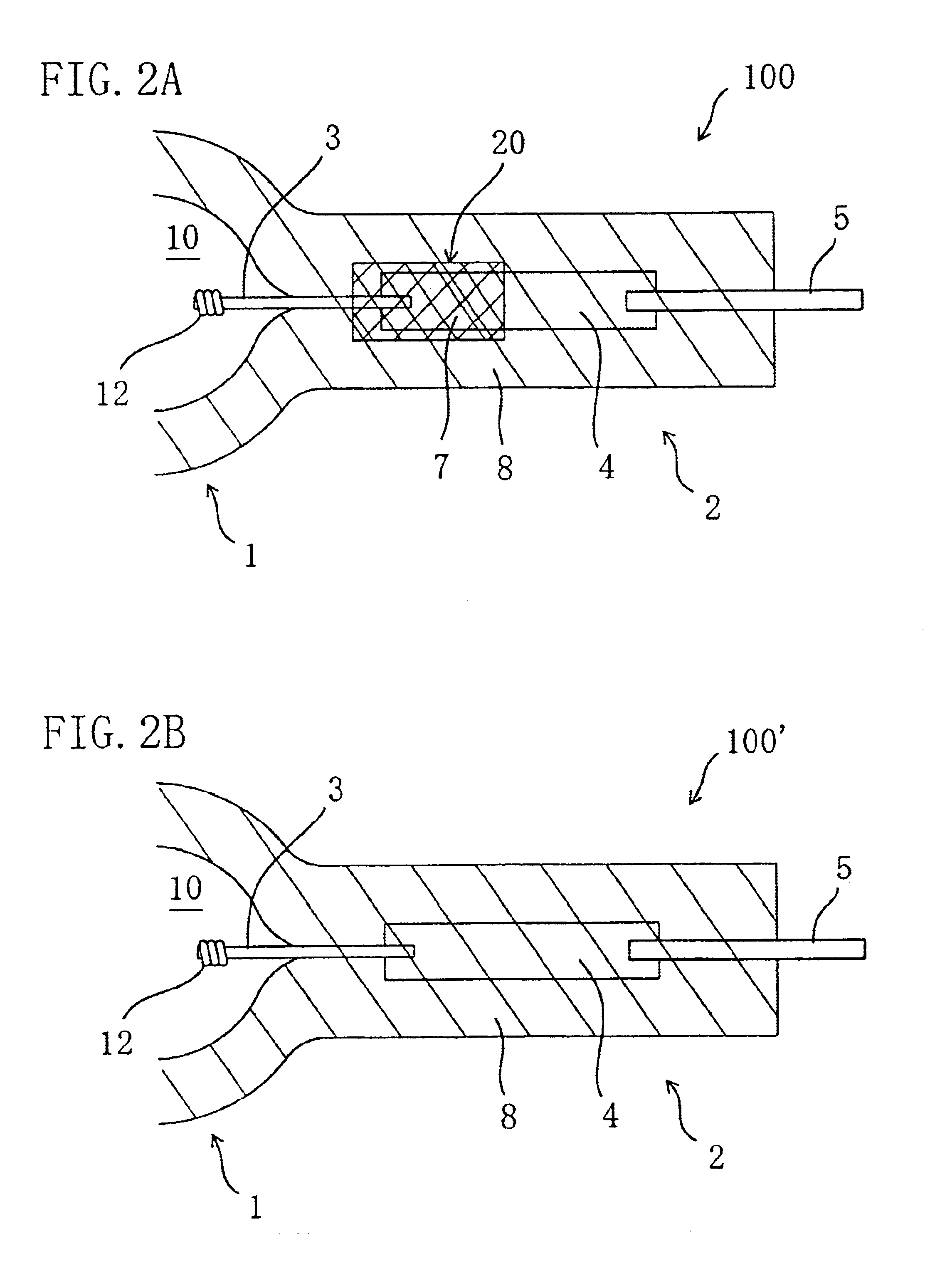
[0097]The sealing portion 2 of the lamp 100 is a portion for retaining airtightness of the internal portion 10 of the luminous bulb 1, and the lamp 100 is a double end type lamp provided with two sealing portions 2. The sealing portion 2 includes a first glass portion (side tube portion) 8 extending from the luminous bulb 1 and a second glass portion 7 provided at least in a portion inside (on the side of the center) of the first glass portion 8. The...


PUM


Abstract

A high pressure discharge lamp includes a luminous bulb enclosing a luminous substance therein; and a sealing portion for retaining airtightness of the luminous bulb. The sealing portion has a first glass portion extending from the luminous bulb and a second glass portion provided at least in a portion inside the first glass portion, and the sealing portion has a portion to which a compressive stress is applied.

Description

BACKGROUND OF THE INVENTION[0001]The present invention relates to a high pressure discharge lamp and a lamp unit. In particular, the present invention relates to a high pressure discharge lamp used for general illumination, projectors in combination with a reflecting mirror, headlights of automobiles or the like.[0002]In recent years, an image projecting apparatus such as a liquid crystal projector and a DMD projector is commonly used as a system for realizing large-scale video images, and in general, a high pressure discharge lamp having a high intensity is commonly used for such an image projecting apparatus. FIG. 40 is a schematic view showing the structure of a conventional high pressure discharge lamp 1000. The lamp 1000 shown in FIG. 40 is a so-called superhigh pressure mercury lamp is disclosed, for example, in Japanese Laid-Open Patent Publication No. 2-148561.[0003]The lamp 1000 includes a luminous bulb (arc tube) 101 made of quartz glass and a pair of sealing portions (sea...

Claims


Application Information

Patent Timeline
Patent Type & Authority Patents(United States)
IPC IPC(8): H01J61/00H01J61/36H01J61/20H01J61/30H01J61/12H01J61/82H01J9/00H01J17/02H01J17/18H01J9/32H05B33/10H01J61/073
CPCH01J61/366H01J61/073
Inventor HATAOKA, SHINICHIROTAKAHASHI, KIYOSHIKANEKO, YURIKOHORIUCHI, MAKOTOKAI, MAKOTOICHIBAKASE, TSUYOSHISEKI, TOMOYUKI
Owner PANASONIC CORP
Why Eureka
Try Eureka