
Dual-frequency-illuminating reflector

a reflector and dual-frequency technology, applied in the field of satellite communication systems, can solve the problems of increasing the cost of launch as well as the cost of design and manufacture, and adding additional weight to the traditional satellite, and achieve the effects of low cost of manufacture and launch, fast acquisition, and light weigh

Active Publication Date: 2005-11-15
LOCKHEED MARTIN CORP
View PDF3 Cites 17 Cited by
  • Summary
  • Abstract
  • Description
  • Claims
  • Application Information

AI Technical Summary

Benefits of technology

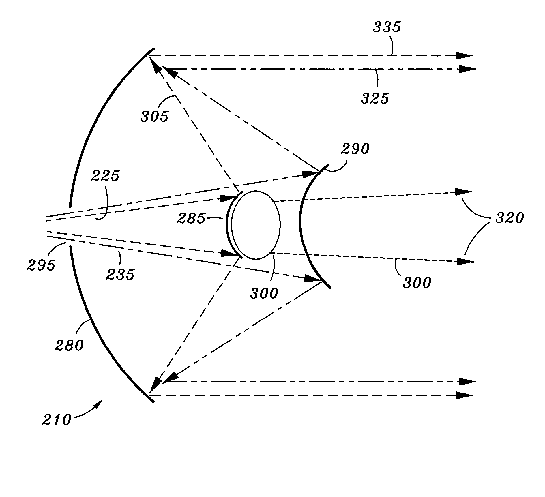
[0008]Numerous benefits may be achieved using embodiments of the present invention over conventional techniques. For example, an embodiment of the invention provides for transmitting first and second frequency bands employing a single illuminating reflector, thereby providing a satellite that is relatively light weight and accordingly relatively inexpensive to manufacture and launch. The embodiment provides that at least one of the frequency bands is transmitted in an dispersed beam and a collimated beam providing for fast acquisition and tracking of transmitted frequency bands. As the illuminating reflector is configured to transmit two or more frequency bands, communications having a variety data transmission rates may be transmitted providing high and low rates of information transmission to other satellites and to terrestrial receivers. In other embodiments, the invention provides transmission and reception of multiple frequencies with a single illuminating reflector. Depending upon the specific embodiment, there can be one or more of these benefits. These and other benefits can be found throughout the present specification and more particularly below.

Problems solved by technology

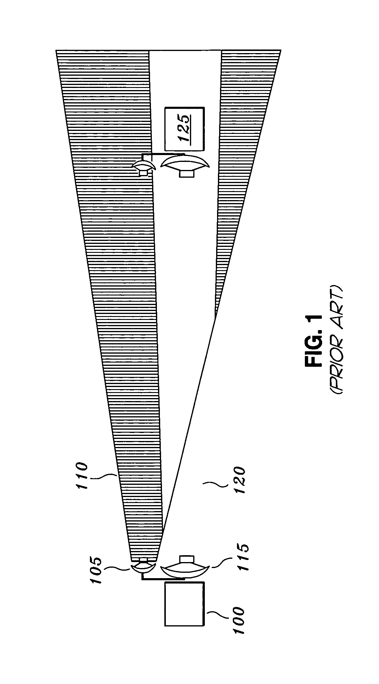
Because two transmitters are typically used to transmit dispersed and collimated beams, additional weight is added to the traditional satellite that raises the cost of launch as well as the cost of design and manufacture.

Method used


Image

  • Dual-frequency-illuminating reflector
  • Dual-frequency-illuminating reflector
  • Dual-frequency-illuminating reflector

Examples


Embodiment Construction

[0018]The present invention provides a satellite communication system. More particularly the present invention provides a dual-frequency-illuminating reflector that provides cross-link communications with other satellites and provides terrestrial communications.

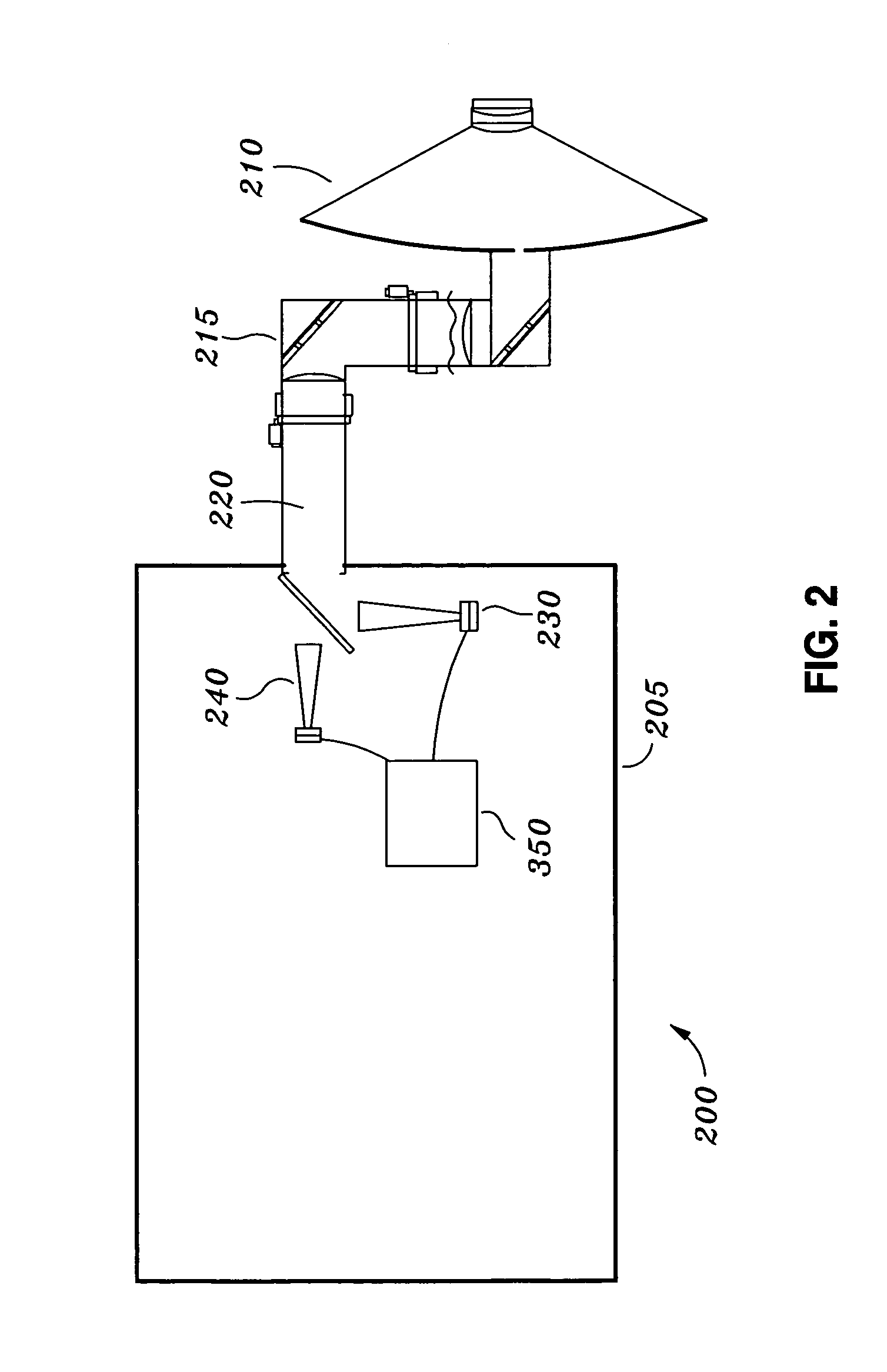
[0019]FIG. 2 is a simplified schematic of a satellite 200 according to an embodiment of the present invention. Satellite 200 includes a satellite bus 205 and an illuminating reflector 210. Satellite bus 205 is coupled to illuminating reflector 210 via a control arm 215. Control arm 215 may have one or more gimbals configured to rotate (or slew) illuminating reflector 210. Control arm 215 may include a beam waveguide 220 configured to deliver two or more frequency bands of electromagnetic radiation from the satellite bus to the illuminating reflector.

[0020]FIG. 3 is a detailed schematic of control arm 215 and illuminating reflector 210 according to an embodiment of the present invention. The control arm and illuminating reflec...


PUM


Abstract

An illuminating reflector system is provided for transmitting first and second frequency bands for satellite and terrestrial communications. The illuminating reflector includes a first reflector configured to transmit a first portion of the first frequency band in an dispersed beam, to reflect a second portion of the first frequency band, and to transmit the second frequency band; a second reflector configured to reflect the second frequency band received from the first reflector; and a primary reflector configured to receive the second portion of the first frequency band reflected from the first reflector, to receive the second frequency band reflected from the second reflector, and to reflect the second portion of the first frequency band and the second frequency band in a substantially collimated beam.

Description

BACKGROUND OF THE INVENTION[0001]The present invention relates to satellite communication systems. More particularly the present invention relates to a dual-frequency-illuminating reflector that provides cross-link communications with other satellites and provides terrestrial communications.[0002]Modern satellites provide high bandwidth communications for military applications, telecommunications, and television as well as others fields. Costs associated with launching satellites into Earth orbits increase significantly in proportion to increased satellite weight. Accordingly, one goal of satellite manufacturers is to manufacture satellites as light as feasibly possible while continuing to provide high bandwidth communications.[0003]A traditional satellite in cross-communication with other satellites typically transmit a frequency band through two transmitters. The frequency band is typically transmitted as an dispersed beam by a first transmitter and as a collimated beam by a secon...

Claims


Application Information

Patent Timeline
Patent Type & Authority Patents(United States)
IPC IPC(8): H01Q13/00H01Q1/28H01Q5/00H01Q5/55H01Q15/00H01Q19/19
CPCH01Q1/288H01Q5/55H01Q15/0033H01Q19/191
Inventor MILLER, JULIETAFT, WILLIAM J.
Owner LOCKHEED MARTIN CORP
Learn More