Multiple frequency band antenna and signal receiving system using such antenna

a multi-frequency band antenna and antenna technology, applied in the structural form of resonant antennas polarised antenna units, etc., can solve the problems of troublesome electrical control of load impedance, inability to receive radio waves in a plurality of frequency bands,

Inactive Publication Date: 2005-11-15
DX ANTENNA CO LTD
View PDF3 Cites 78 Cited by
  • Summary
  • Abstract
  • Description
  • Claims
  • Application Information

AI Technical Summary

Benefits of technology

[0007]A reactance element may be connected in parallel with each of the first and second switch devices. The values of the reactance elements are so selected that the dipole antenna is substantially disconnected from the extension elements in the first frequency band, and that the dipole antenna is substantially connected to the respective extension elements in the second frequency band. Furthermore, the values of the reactance elements, when the sum of the dipole antenna elements and the extension elements is shorter than the length required for receiving radio waves in the second frequency band, may be determined such that the reactance elements can provide loading effect that can make it possible to receive well radio waves in the second frequency band. The control means causes the first and second switch devices to be opened when a radio wave in the second frequency band is received.

Problems solved by technology

The dipole antenna according to the handbook can receive radio waves only in a single frequency band, but it cannot be used to receive radio waves in a plurality of frequency bands.
Furthermore, electrical control of the load impedance is troublesome.

Method used


Image

  • Multiple frequency band antenna and signal receiving system using such antenna
  • Multiple frequency band antenna and signal receiving system using such antenna
  • Multiple frequency band antenna and signal receiving system using such antenna

Examples


first embodiment

[0032]A multiple frequency band antenna according to the present invention is arranged to receive radio waves in a first frequency band or UHF band, for example, ranging from 470 MHz to 890 MHz, and in a second frequency band or VHF band, for example, ranging from 54 MHz to 216 MHz. In addition, the multiple frequency band antenna has its directivity variable in the UHF and VHF bands, in a plurality of steps spaced by a predetermined amount, in sixteen (16) steps spaced by an angle of 22.5°, for example.

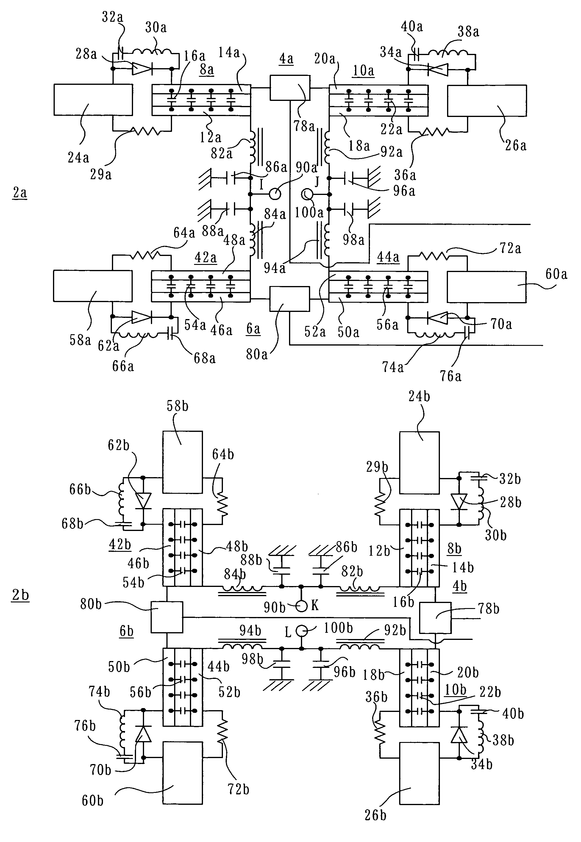
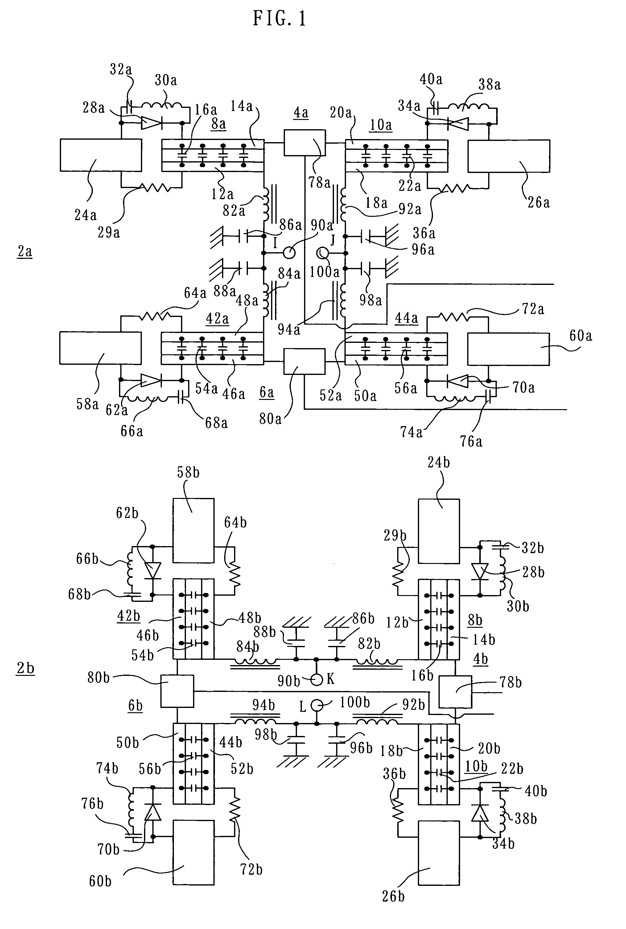
[0033]As shown in FIG. 1, the multiple frequency band antenna according to the first embodiment has an antenna group including a first antenna 2a and a second antenna 2b.

[0034]The first antenna 2a may be formed on a printed circuit board (not shown), for example, and includes first and second dipole antennas 4a and 6a.

[0035]The first dipole antenna 4a includes dipole antenna elements 8a and 10a, which are arranged on a single straight line and have the same length. The length of th...

second embodiment

[0072]As shown in FIG. 10, in the multiple frequency band antenna the variable phase shifter 300a is connected between the output of the variable attenuator 136a and the input of the combiner 138. Similarly, the variable phase shifter 300b is connected between the output of the variable attenuator 136b and the input of the combiner 138.

[0073]The variable phase shifters 300a and 300b have the same configuration as the first phase circuit of the variable phase shifter 106a. Accordingly, when a H-level voltage is applied to a voltage supply terminal 302a, a current flows through a resistor 304a and PIN diodes 306a and 308a, so that the output signal of the variable attenuator 136a is applied as it is to the combiner 138. On the other hand, if a H-level voltage is applied to a voltage supply terminal 310a, a current flows through a resistor 312a, a PIN diode 314a and a high-frequency blocking coil 316a, and also a current flows through the resistor 312a, a phase shifter 318a, a PIN dio...

third embodiment

[0092]In the third embodiment, the antenna control commander 534 is described to be external to the signal receiving apparatus 518, but it may be provided in the signal receiving apparatus 518.


PUM


Abstract

A multiple frequency band antenna includes a dipole antenna (4a), which is formed of two dipole antenna elements (8a, 10a). Two extension elements (24a, 26a) extend outward from respective ones of opposed outer ends of the dipole antenna (4a). The length of the dipole antenna (4a) is determined to make the multiple frequency band antenna capable of receiving radio waves in the UHF band, and the sum of the lengths of the dipole antenna (4a) and the extension elements (24a, 26a) is determined to make the multiple frequency band antenna capable of receiving radio waves in the VHF band. PIN diodes (28a, 34a) are connected between the respective extension elements (24a, 26a) and the respective outer ends of the dipole antenna (4a). When a radio wave in the UHF band is to be received, a control unit (180) places the diodes (28a, 34a) selectively in a state in which both are opened, a state in which one of the diodes (28a) is closed while the other (34a) is opened, and a state in which the one diode (28a) is opened while the other (34a) is closed.

Description

[0001]This invention relates to a multiple frequency band antenna capable of receiving radio waves in a plurality of frequency bands, and, more particularly, to such an antenna having a directivity which is variable in at least one frequency band.BACKGROUND OF THE INVENTION[0002]A variable directivity antenna is known, which has its directivity variable to a direction from which a desired radio wave comes. An example of such variable directivity antennas is a dipole antenna with an asymmetrically loaded feed point disclosed in Page 43 of a book “Antenna Engineering Handbook”, First Edition, Eleventh Print, published on Jan. 25, 2001 from The Institute of Electronics, Information and Communication Engineers of Japan.[0003]According to the technique disclosed in this book, a location to be basically fed of a 1.5 wavelength or 2 wavelength multiple-feed point dipole antenna, which is to be fed at a plurality of locations and, therefore, tends to need a relatively complicated feeding sy...

Claims


Application Information

Patent Timeline
Patent Type & Authority Patents(United States)
IPC IPC(8): H01Q21/00H01Q9/14H01Q9/28H01Q9/04H01Q3/30H01Q21/30H01Q3/24H01Q9/16H01Q3/36H01Q1/38H01Q3/26H01Q5/10H01Q5/321H01Q21/26
CPCH01Q1/38H01Q3/2605H01Q9/14H01Q9/285H01Q21/26
Inventor SHIROSAKA, TOSHIAKIFUJITA, TOSHIOTATEKAWA, KIYOTAKAFUJISAWA, SHINGOSHIBUYA, EIJI
Owner DX ANTENNA CO LTD
Why Eureka
Try Eureka