Communication apparatus and transmission technique selection method

Inactive Publication Date: 2005-11-15
PANASONIC INTELLECTUAL PROPERTY CORP OF AMERICA
View PDF10 Cites 16 Cited by
  • Summary
  • Abstract
  • Description
  • Claims
  • Application Information

AI Technical Summary

Benefits of technology

[0037]A first object of the present invention is to provide a communication apparatus and a transmission technique selection method to reduce the communic

Problems solved by technology

However, because the selected information shows the signal transmitted with a transmission technique which can be selected among all transmission techniques in the conventional apparatus is transmitted to a communication partner, the kinds of information of the selected transmission method increases and the data capacity used for distinguishing the information of such selected transmission method becomes large, hence, there is a pro

Method used


Image

  • Communication apparatus and transmission technique selection method
  • Communication apparatus and transmission technique selection method
  • Communication apparatus and transmission technique selection method

Examples


embodiment 1

(Embodiment 1)

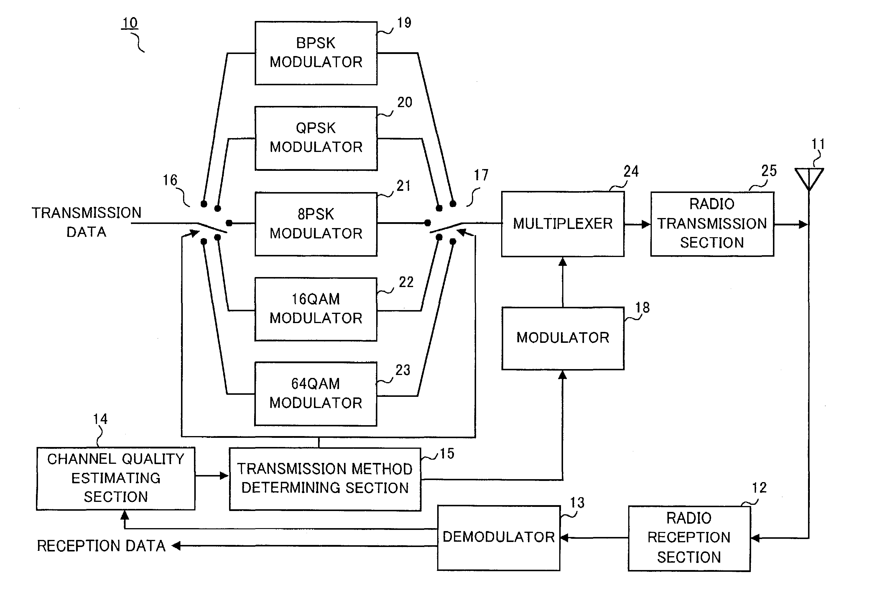
[0055]FIG. 6 is a block diagram showing a configuration of a communication apparatus according to Embodiment 1 of the present invention;

[0056]In FIG. 6, a communication terminal 100 mainly comprises antenna 101, radio reception section 102, demodulator 103, channel quality estimating section 104, transmission method determining section 105, switch 106, switch 107, control signal dividing section 108, BPSK modulator 109, QPSK modulator 110, 8PSK modulator 111, 16QAM modulator 112, 64QAM modulator 113, modulator 114, multiplexer 115 and radio transmission section 116.

[0057]Radio reception section 102 receives a radio signal via antenna 101, carries out predetermined radio reception processing and outputs the received signal to demodulator 103. Demodulator 103 demodulates the received signal, separates the received data and the estimation value of the received signal quality which is estimated in reception quality estimating section 163 of the reception side as to be desc...

embodiment 2

(Embodiment 2)

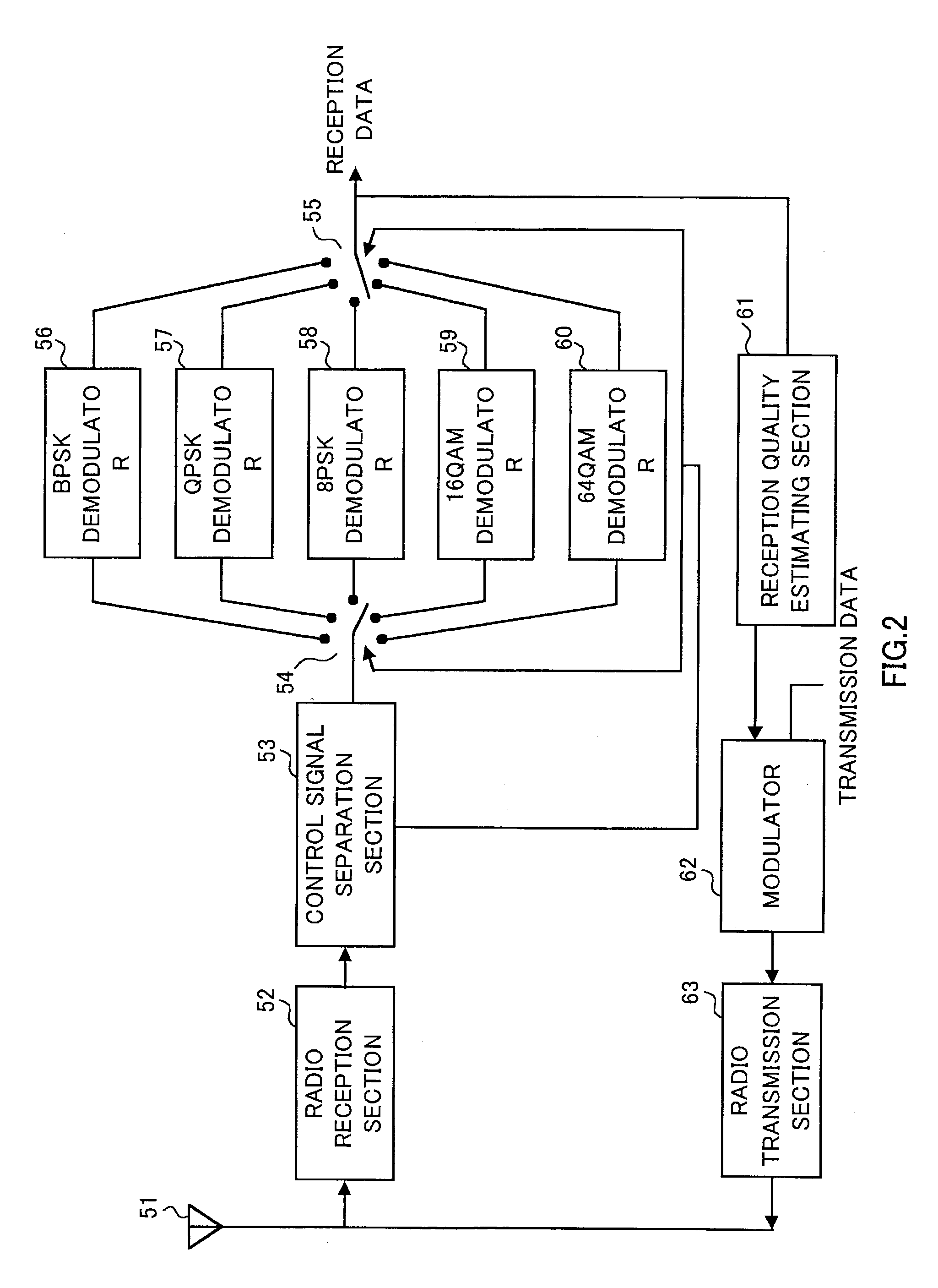
[0114]FIG. 12 is a block diagram showing a configuration of a communication apparatus according to Embodiment 2 of the present invention. However, the sections similar to those shown in FIG. 6 are assigned the same reference numerals and explanation thereof will be omitted.

[0115]Communication apparatus 200 shown in FIG. 12 comprises control signal dividing section 201, and divides the transmission methods into a plurality of groups, determines the group information in which a selected transmission method is included, transmits only the group information when group information are updated, and does not transmit information which shows a specific transmission method among the group which is a different point from the communication apparatus shown in FIG. 6.

[0116]Channel quality estimating section 104 estimates the channel quality from the quality estimation value of the reception signal separated in demodulator 103 and outputs the result to transmission method determinin...


PUM


Abstract

Channel quality estimating section 104 estimates the channel quality from the reception signal quality and outputs the result to transmission method determining section 105 and control signal dividing section 108. Transmission method determining section 105 determines a transmission method of a signal transmitted to communication partner from channel conditions and outputs the result to switch 106, switch 107 and control signal dividing section 108. Control signal dividing section 108 divides the transmission method information into high-speed control signal which is transmitted periodically and low-speed control signal which is transmitted on demand rather than periodically. Moreover, control signal dividing section 108 determines the combinations of low-speed control signal and high-speed control signal outputted from a tendency of communication quality, and outputs the result to modulator 114. Modulator 114 modulates the high-speed control signal and low-speed control signal, and outputs the result to multiplexer 115.

Description

TECHNICAL FIELD[0001]The present invention relates to a communication apparatus and a transmission technique selection method, in particular, relates to a communication apparatus and a transmission technique selection method that preferably used for an adaptive modulation to improve transmission efficiency of packet communication, etc.BACKGROUND ART[0002]With the recent development of an Internet related art, it becomes possible to provide on the internet several kinds of services such as music on demand. In such a service, the transmission capacity of downlink channel is greatly increased. It is largely expected that high speed transmission in the downlink channel is to be achieved in order to realize services with large transmission capacity of the downlink channel. In addition, several technology developments are undergone on high speed transmission in downlink channel. As one technology of high speed transmission in downlink channel, a modulation method is adaptively updated in ...

Claims


Application Information

Patent Timeline
IPC IPC(8): H04L1/00H04L27/00H04B7/26H04L27/18H04L27/34
CPCH04L1/0003H04L1/0025H04L1/0026H04L1/0027H04L1/0029H04L27/0008H04L27/0012Y02B60/31Y02D30/50H04B7/005
Inventor UESUGI, MITSURU
Owner PANASONIC INTELLECTUAL PROPERTY CORP OF AMERICA
Why Eureka
Try Eureka