
Piezoelectric electro-acoustic transducer

a technology of electroacoustic transducers and electroacoustic transducers, which is applied in piezoelectric/electrostrictive transducers, generators/motors, and cylindrical diaphragms. it can solve the problems of increasing resonance frequency, difficult to provide vibration plates having a reduced size, and low acoustic conversion efficiency, so as to reduce size and resonance frequency, wide-band speech, and increase displacement

Active Publication Date: 2005-11-15
MURATA MFG CO LTD
View PDF5 Cites 15 Cited by
  • Summary
  • Abstract
  • Description
  • Claims
  • Application Information

AI Technical Summary

Benefits of technology

[0013]To overcome the problems described above, preferred embodiments of the present invention provide a piezoelectric electro-acoustic transducer having a reduced size and resonance frequency, an increased displacement, and which is capable of reproducing a wide band speech.

Problems solved by technology

Accordingly, the acoustic conversion efficiency is low.
It is difficult to provide a vibration plate having a reduced size and also provide a sound pressure characteristic including a low resonance frequency.
The above-described piezoelectric vibration plate, although it has a high acoustic conversion efficiency, has problems in that when the vibration plate is supported in a case, the periphery of the vibration plate must be closely sealed, which increases the resonance frequency.
However, according to the above-described supporting structure, a substantially flat sound pressure characteristic in a wide band cannot be achieved.
Thus, a desired speaker characteristic cannot be attained in some cases.
Moreover, if the sheet member is excessively large as compared to the vibration plate, an effective sound pressure characteristic cannot be attained, and the size of an electro-acoustic transducer is increased.

Method used


Image

  • Piezoelectric electro-acoustic transducer
  • Piezoelectric electro-acoustic transducer
  • Piezoelectric electro-acoustic transducer

Examples


Embodiment Construction

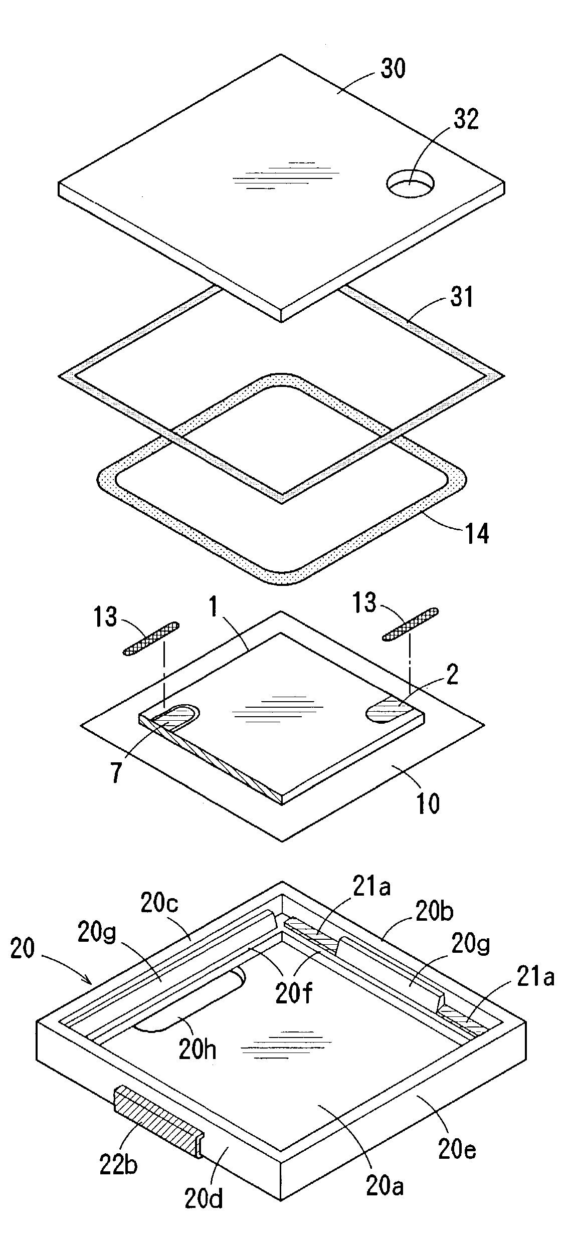
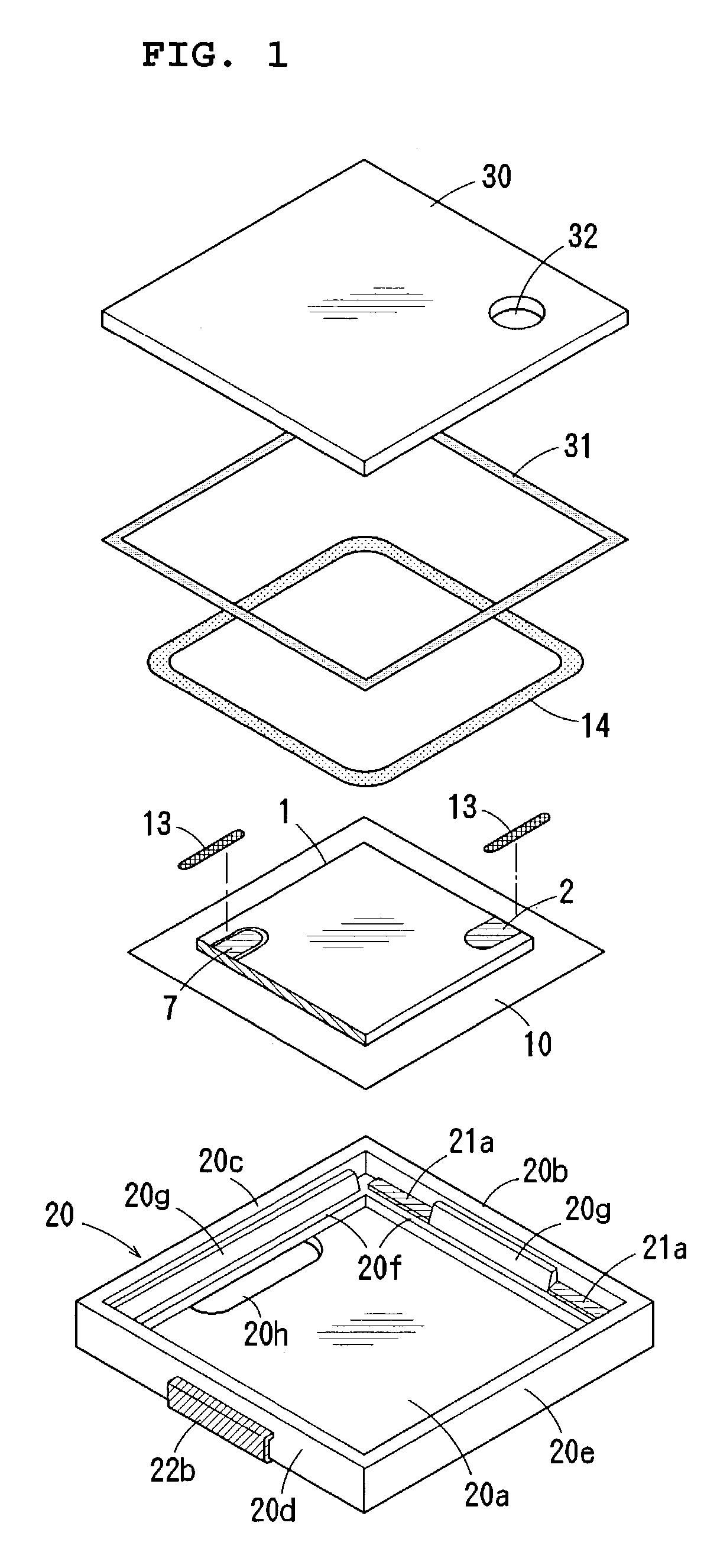
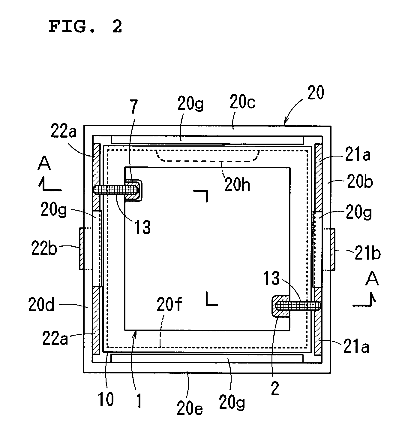
[0059]FIGS. 1 to 7 show a surface-mounting type piezoelectric electro-acoustic transducer according to a first preferred embodiment of the present invention.

[0060]The electro-acoustic transducer according to this preferred embodiment, such as a piezoelectric receiver, reproduces a wide-band speech having a substantially flat sound pressure characteristic in a human speech band (300 Hz to 3.4 kHz). The transducer includes a piezoelectric vibration plate 1 having a laminated structure, a resin film 10, a case 20, and a cover 30. Here, a casing includes the case 20 and the cover 30.

[0061]The vibration plate 1 is formed preferably by laminating two layers, that is, piezoelectric ceramic layers 1a and 1b, as shown in FIGS. 5 to 7. Main surface electrodes 2 and 3 are provided on the front and back main surfaces of the piezoelectric vibration plate 1, respectively. An internal electrode 4 is provided between the ceramic layers 1a and 1b. The two ceramic layers 1a and 1b are polarized prefe...


PUM


Abstract

A piezoelectric electro-acoustic transducer includes a piezoelectric vibration plate having a plurality of piezoelectric ceramic layers laminated to each other with an internal electrode being interposed between the ceramic layers, and main surface electrodes provided on the front and back surfaces thereof, whereby area bending vibration is produced by applying an AC signal between the main surface electrodes and the internal electrode, respectively, a resin film having a size that is greater than the piezoelectric vibration plate and having the piezoelectric vibration plate bonded substantially to the central portion of the surface thereof, and a casing which accommodates the piezoelectric vibration plate and the resin film. The piezoelectric vibration plate has an area of about 40% to about 70% of that of the resin film. The inner peripheral surface of the case is provided with a supporting portion having a frame shape that is larger than that of the piezoelectric vibration plate, and the outer peripheral portion of the resin film having no piezoelectric vibration plate bonded thereto is supported by the supporting portion of the case.

Description

BACKGROUND OF THE INVENTION[0001]1. Field of the Invention[0002]The present invention relates to a piezoelectric electro-acoustic transducer such as a piezoelectric receiver, a piezoelectric sounder, or a piezoelectric speaker.[0003]2. Background of the Invention[0004]In electronic devices and apparatuses, such as household electronic appliances and portable telephones, electro-acoustic transducers have been widely used as piezoelectric sounders to generate acoustic alarms or operational sounds and piezoelectric receivers.[0005]Generally, such an electro-acoustic transducer includes a piezoelectric plate that is bonded to one side or both sides of a metallic sheet to define a vibration plate, the periphery of the metallic sheet is bonded and fixed to a case, and the opening of the case is closed with a cover.[0006]For such vibration plates as described above, a piezoelectric plate which radially vibrates is constrained by the metallic plate which suffers no area-changes, such that a...

Claims


Application Information

Patent Timeline
IPC IPC(8): H04R17/00H01L41/083H01L41/09
CPCH04R1/06H04R17/00H04R31/003H04R2307/023
Inventor YAMAUCHI, MASAKAZUTAKESHIMA, TETSUOSUMITA, MANABU
Owner MURATA MFG CO LTD
Learn More