Wind turbine having airfoils for blocking and directing wind and rotors with or without a central gap

a technology of wind turbines and airfoils, applied in the field of cross-flow wind turbines, can solve the problems of high initial cost and limited efficiency of machines, radial windmills cannot normally be operated in very high wind conditions, exposed blades are hazardous to certain wildlife, etc., and achieve the effect of safe and visually appealing

Inactive Publication Date: 2005-11-22
TERRA MOYA AQUA
View PDF87 Cites 59 Cited by
  • Summary
  • Abstract
  • Description
  • Claims
  • Application Information

AI Technical Summary

Benefits of technology

[0011]Advantages of various embodiments of the present invention include the ability ...

Problems solved by technology

These machines often have a high initial cost and have limited efficiency.
Further, the exposed blades are hazardous to certain wildlife such as birds.
In addition, radial w...

Method used


Image

  • Wind turbine having airfoils for blocking and directing wind and rotors with or without a central gap
  • Wind turbine having airfoils for blocking and directing wind and rotors with or without a central gap
  • Wind turbine having airfoils for blocking and directing wind and rotors with or without a central gap

Examples


first embodiment

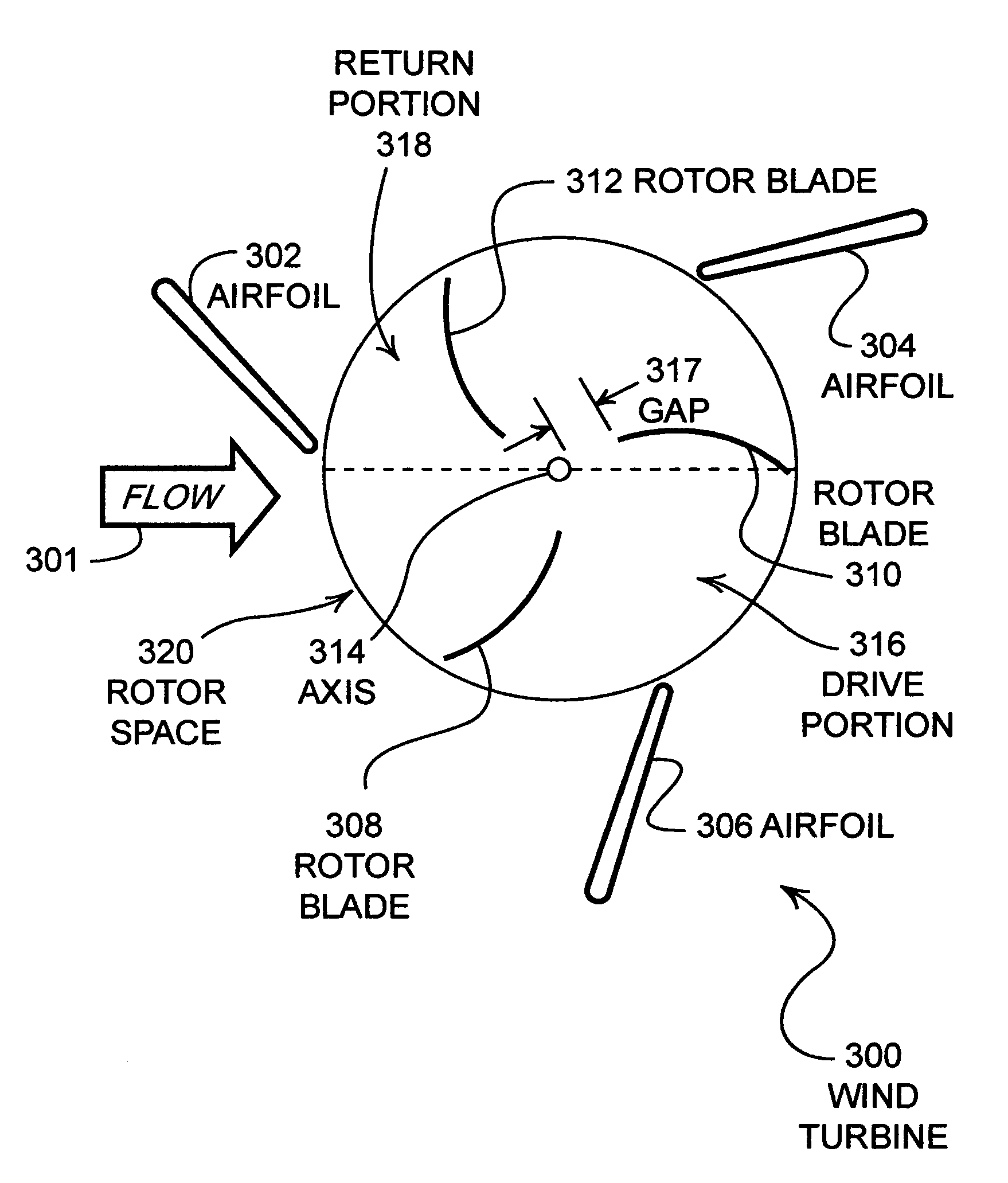
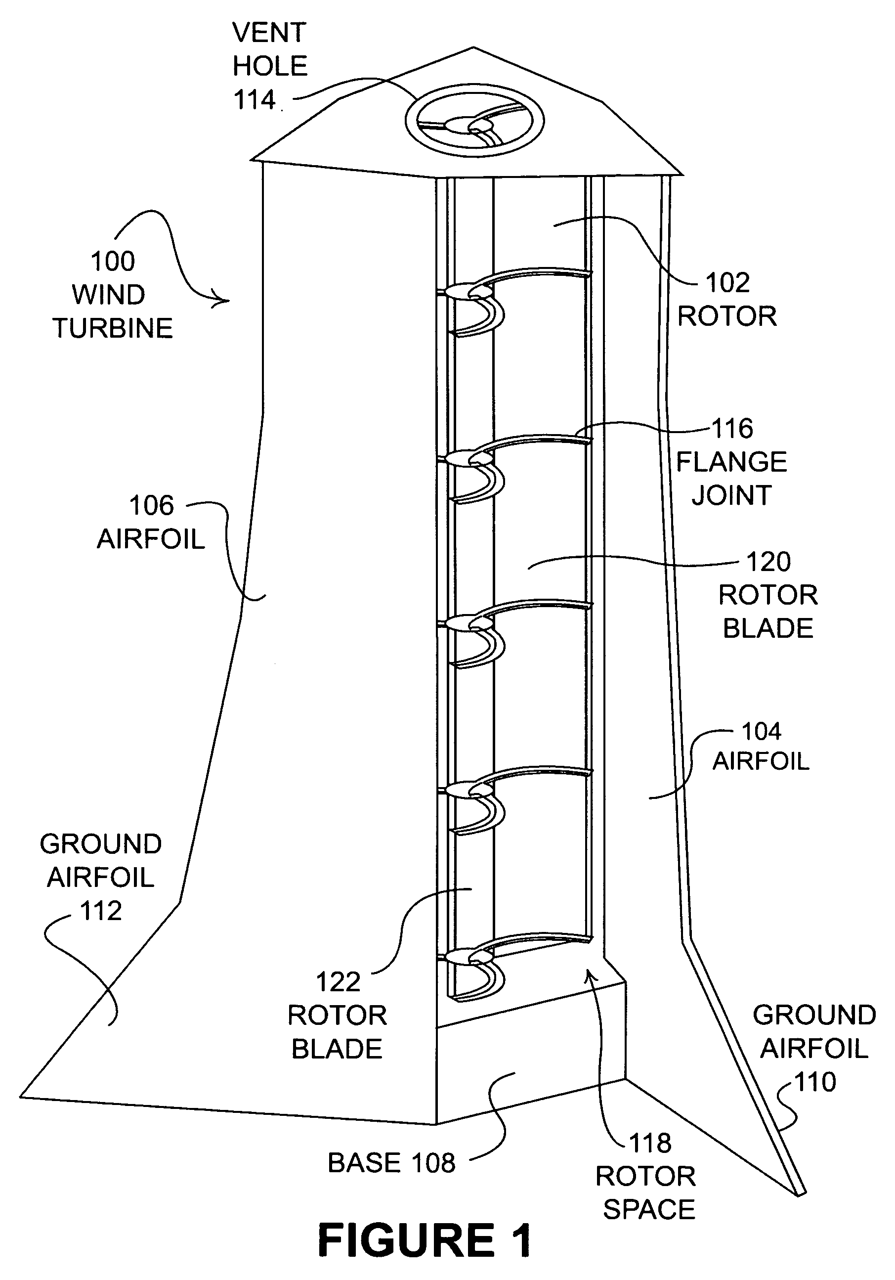
[0026]FIG. 1 is a perspective view of a crossflow wind turbine 100. Crossflow wind turbines differ from propeller type (radial flow) turbines in that the wind generally flows across the axis of rotation in crossflow turbines, rather than generally along the axis of rotation in propeller type turbines. As shown in FIG. 1, a vertical rotor 102 is propelled by the wind and is mechanically coupled to an electrical generator located in the base 108. The rotor 102 is generally disposed with a vertical axis, but can have other orientations as desired. Three airfoils 104, 106, and one not visible behind the rotor 102, serve to support the upper portion of the rotor 102 and also to direct the wind into a drive portion of a rotor space 118 of the rotor 102 for increased efficiency and to block wind from a return portion of the rotor space 118. The rotor space 118 is the volume that is swept out by the rotor blades of rotor 102, such as rotor blades 120, 122, during the rotation of rotor 102. ...

embodiment 600

[0041]The asymmetrical design of the embodiment 600 may be beneficial in locations where the wind is predominately from one direction, which is often the case in locations of high wind. Such embodiments may have the benefit of lower costs, since fewer structural components may be needed to construct the wind turbine. Further, the asymmetric nature of the wind turbine may be optimized for increased performance in the direction of the prevailing wind.

[0042]FIG. 7 illustrates a cross-sectional view of another embodiment of a wind turbine 700. The incoming airflow is represented by arrow 701 from the left side of FIG. 7. Airfoils 702, 704, 706, and 708 are disposed symmetrically on two sides of the rotor space 720. Three rotor blades 710, 712, and 714 are similar in design to those of embodiment 600.

embodiment 700

[0043]Airfoils 702, 704, 706, 708 are disposed in a symmetric design that is capable of capturing wind from two opposing directions. Airfoils 702, 704, 706, 708 are arranged in a manner that provides optimized performance from wind flowing from direction 701 as well as wind flowing from the opposite direction 703. In many locations with high prevailing wind, the wind direction may often be from a primary direction 701. In such locations, the secondary direction is often opposite from the primary direction 701. The embodiment 700 may take advantage of such a phenomena by being oriented to perform at maximum efficiency in the two main wind directions. As shown in FIG. 7, airfoil 702 blocks wind flowing from direction 701 from entering the return portion 718 of the rotor space 720. Airfoil 706 assists in guiding wind flowing from direction 701 into the drive portion 716. Similarly, airfoil 708 blocks wind flowing from direction 703 from the drive portion 716, which becomes the return p...


PUM


Abstract

A wind turbine device of increased efficiency is comprised of a set of fixed airfoils that direct wind into a rotor having a plurality of blades. The fixed airfoils may extend to the ground to increase the amount of wind directed into the rotor and may be manufactured from concrete. The rotor blades have a vented portion near the axis of rotation that has been found to increase efficiency for certain blade geometries. For other blade geometries, increased efficiency is observed with no gap at the axis of rotation. The rotor may also be manufactured from composite materials to increase strength while decreasing the moment of inertia for the rotor.

Description

CROSS REFERENCE TO RELATED CASES[0001]The present patent application is based upon and claims the benefit of U.S. Provisional Patent Application Ser. No. 60 / 467,773, filed on Apr. 30, 2003, entitled “Wind Turbine” by Ronald J. Taylor and Scott J. Taylor, which is hereby specifically incorporated herein by reference for all that it discloses and teaches.BACKGROUND OF THE INVENTION[0002]a. Field of the Invention[0003]The present invention pertains generally to wind turbines and more specifically to crossflow wind turbines having a plurality of stationary airfoils positioned about a rotor having a plurality of blades.[0004]b. Description of the Background[0005]Radial flow windmills that harness wind energy using a plurality of exposed blades have been used both privately and commercially for some time. These machines often have a high initial cost and have limited efficiency. Further, the exposed blades are hazardous to certain wildlife such as birds. In addition, radial windmills cann...

Claims


Application Information

Patent Timeline
IPC IPC(8): F03D3/04F03D3/00
CPCF03D3/0409F05B2240/213Y02E10/74Y10S416/04Y10S415/908Y10S416/09Y02E10/728F03D13/20F03D3/0427Y02P70/50
Inventor TAYLOR, RONALD J.TAYLOR, SCOTT J.
Owner TERRA MOYA AQUA
Why Eureka
Try Eureka