Shift control system of automatic transmission

a technology of automatic transmission and control system, which is applied in the direction of instruments, transportation and packaging, gearing, etc., can solve the problems of over-shock, down spike, up spike, etc., and achieve the effect of reducing the number of component parts and cos

Inactive Publication Date: 2005-11-22
JATCO LTD
View PDF17 Cites 24 Cited by
  • Summary
  • Abstract
  • Description
  • Claims
  • Application Information

AI Technical Summary

Benefits of technology

[0011]In view of the above problems, the present invention has been invented. It is an object of the present invention to provided a shift control system of an automatic transmission that can securely prevent an interlock by eliminating a sleeping failure, and that can secure a high shift controllability which is not, in a period of shift, restricted in terms of hydraulic pressure control range of each of friction elements.

Problems solved by technology

Therefore, the shift control system of the automatic transmission according to the above conventional technology may cause an insensible failure which may be attributable, for example, to the fail safe valve 77 sticking to a spring's extension side (hereinafter, the insensible failure is referred to as a sleeping failure), thus causing an interlock.
In this state, however, the following failures may cause the interlock attributable to simultaneous engagements of a plurality of friction elements: 1. the electric failure, 2. cutting of the duty solenoid SLC1, or 3. the duty solenoid SLC1 sticking to the hydraulic pressure output side.
In addition, the gear change from the fourth speed 4TH, the fifth speed 5TH and the sixth speed 6TH to the sixth speed 6TH in the electric failure involves a maximum gear change of two (fourth speed 4TH to sixth speed 6TH), thus causing an excessive shock (down spike and up spike).
In other words, the gear change in the electric failure from the fourth speed 4TH to the sixth speed 6TH is likely to cause the interlock due to an excessive capacity of both the engagement and disengagement as is seen in FIG. 10, thus causing the down spike.
Moreover, a momentary great change in turbine speed may cause the up spike.

Method used


Image

  • Shift control system of automatic transmission
  • Shift control system of automatic transmission
  • Shift control system of automatic transmission

Examples


Embodiment Construction

[0069]Hereinafter described based on drawings is a mode for carrying out the present invention, corresponding to claim 1 to claim 6, which mode achieves a shift control system of an automatic transmission.

(First Mode for Carrying Out)

[0070]Described at first is a constitution.

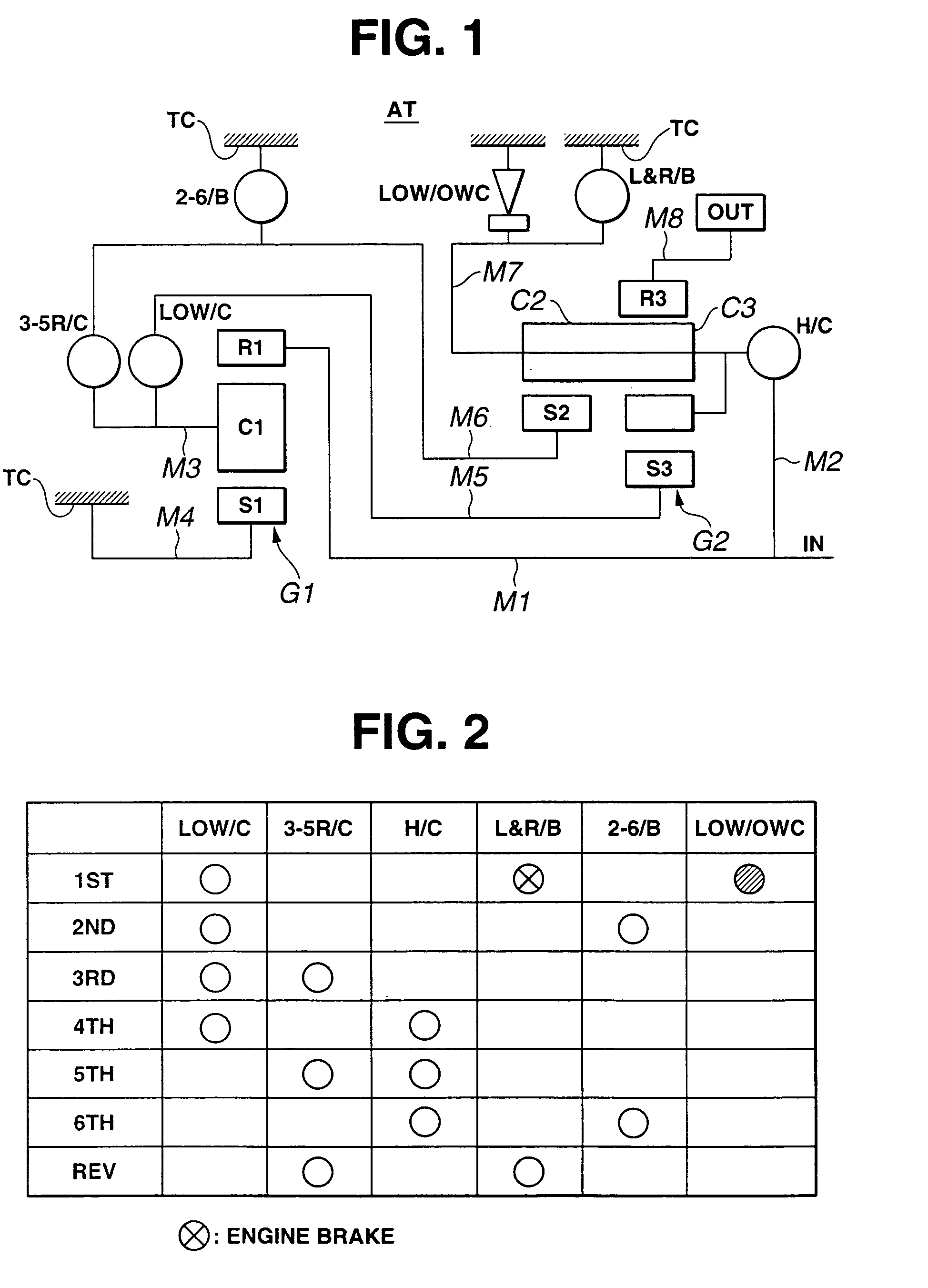
[0071]FIG. 1 is a skeleton diagram showing a gear train of an automatic transmission having six forward gears and one reverse gear, where a shift control system according to the mode for carrying out is applied to the automatic transmission. The automatic transmission uses, as the gear train, a combination of one simple planet gear set G1 and one Ravigneaux gear set G2. The simple planet gear set G1 is constituted of a first sun gear S1, a first carrier C1, and a first ring gear R1. The Ravigneaux gear set G2 is constituted of a second sun gear S2, a second carrier C2, a third sun gear S3, a third carrier C3, and a third ring gear R3.

[0072]Moreover, there is provided an input shaft IN to which an engine driving...


PUM


Abstract

In a case of an electric failure caused to a traveling vehicle and when any of forward gears is held at a step S5, a comparison is made between: 1) a supposedly-engaged friction element of friction elements which is supposed to be engaged at the any of the forward gears and 2) an actually-engaged friction element of the friction elements which is sensed to be actually engaged, the sensing being based on a switch signal from a first hydraulic pressure switch 11, a second hydraulic pressure switch 12, a third hydraulic pressure switch 13, a fourth hydraulic pressure switch 14 and a fifth hydraulic pressure switch 15. When the supposedly-engaged friction element is not in accordance with the actually-engaged friction element, an electric system is determined to be in failure. In the case of the electric failure, a routine moves to a step S6 and subsequent steps for sticking the gear of an automatic transmission to a given gear.As described above, a shift control system of the automatic transmission is thus provided that can eliminate a sleeping failure thereby securely preventing an interlock and that can secure a high shift controllability which is not, in a period of shift, restricted in terms of hydraulic pressure control range of each of the friction elements.

Description

TECHNICAL FIELD[0001]The present invention relates to a shift control system of an automatic transmission having a hydraulic pressure circuit which is constituted of solenoid hydraulic pressure control valves for controlling individually an engagement pressure and a disengagement pressure to a plurality of friction elements related to shift of the automatic transmission.BACKGROUND TECHNIQUE[0002]A conventionally known shift control system of an automatic transmission is disclosed in Japanese Patent Unexamined Publication No. 2000-240776.[0003]Described in the above publication includes a technology for changing gear from first speed 1ST, second speed 2ND and third speed 3RD to third speed 3RD and from fourth speed 4TH, fifth 5TH and sixth speed 6TH to sixth speed 6TH in a case of an electric failure caused to a traveling vehicle.[0004]Thereby, change of a gear to lower than a gear of the traveling vehicle can be avoided, thus preventing sudden engine brake or engine's excessive high...

Claims


Application Information

Patent Timeline
Patent Type & Authority Patents(United States)
IPC IPC(8): F16H61/12F16H3/66F16H61/02F16H3/44F16H59/68F16H59/70F16H61/68F16H61/684F16H61/686F16H63/12
CPCF16H61/12F16H3/663Y10T477/6934F16H61/686F16H2059/6807F16H2061/1208F16H2061/1224F16H2061/1244F16H2200/2097F16H2061/1268F16H2061/1236F16H2059/683Y10S477/906F16H2061/0209F16H61/0206
Inventor INUTA, YUKIYOSHI
Owner JATCO LTD
Why Eureka
Try Eureka