Shield cable method of manufacturing shield cable, and discharge lamp lighting device using shield cable

a shield cable and shield cable technology, applied in the direction of power cables, cables, coupling devices, etc., can solve the problems of obviating a step, and achieve the effect of simplifying the die for the shield and easy grounding

Inactive Publication Date: 2005-11-22
MITSUBISHI ELECTRIC CORP
View PDF11 Cites 21 Cited by
  • Summary
  • Abstract
  • Description
  • Claims
  • Application Information

AI Technical Summary

Benefits of technology

[0025]Further, the second conductor is preferably spirally wound inside the shield, thus making larger the contact area between the second conductor and the shield.
[0026]Still further, the second conductor is preferably able to take out from the shield, thus enabling adjustment of the length of the second conductor at need, and making the second conductor attachable to various devices.
[0027]A lighting device for a discharge lamp of the invention is used for a headlamp of a vehicle and employs a shielding wire. The device includes a bulb socket for the headlamp; a driving power circuit for the headlamp; and a shielding wire for connecting the bulb socket and the driving power circuit. The shielding wire has a first conductor for supplying alternating current from the driving power circuit to the bulb socket and a shield for sheathing the first conductor. The shielding wire has a second conductor laid along the shield so as to be in contact with the shield. Therefore, this shields the electromagnetic waves to be generated by the alternating current supplied from the driving power circuit by a simple structure.
[0028]Further, since the second conductor is preferably grounded to a vehicle body, thus easily grounding the shield to the vehicle body and further ensuring shielding of the first conductor by the shield.
[0029]A method of the invention is intended for manufacturing of a shielding wire including a first conductor; a shield for sheathing the first conductor through an insulating member; a second conductor laid along the inside of the shield so as to be in contact with the shield; and a bundled portion for bundling the shield, the first conductor and the second cond

Problems solved by technology

Further, this obviates a step of inserting the second conductor in

Method used


Image

  • Shield cable method of manufacturing shield cable, and discharge lamp lighting device using shield cable
  • Shield cable method of manufacturing shield cable, and discharge lamp lighting device using shield cable
  • Shield cable method of manufacturing shield cable, and discharge lamp lighting device using shield cable

Examples


first embodiment

[0052]FIGS. 3 through 6 are intended for explaining the shielding wire of the first embodiment of the invention.

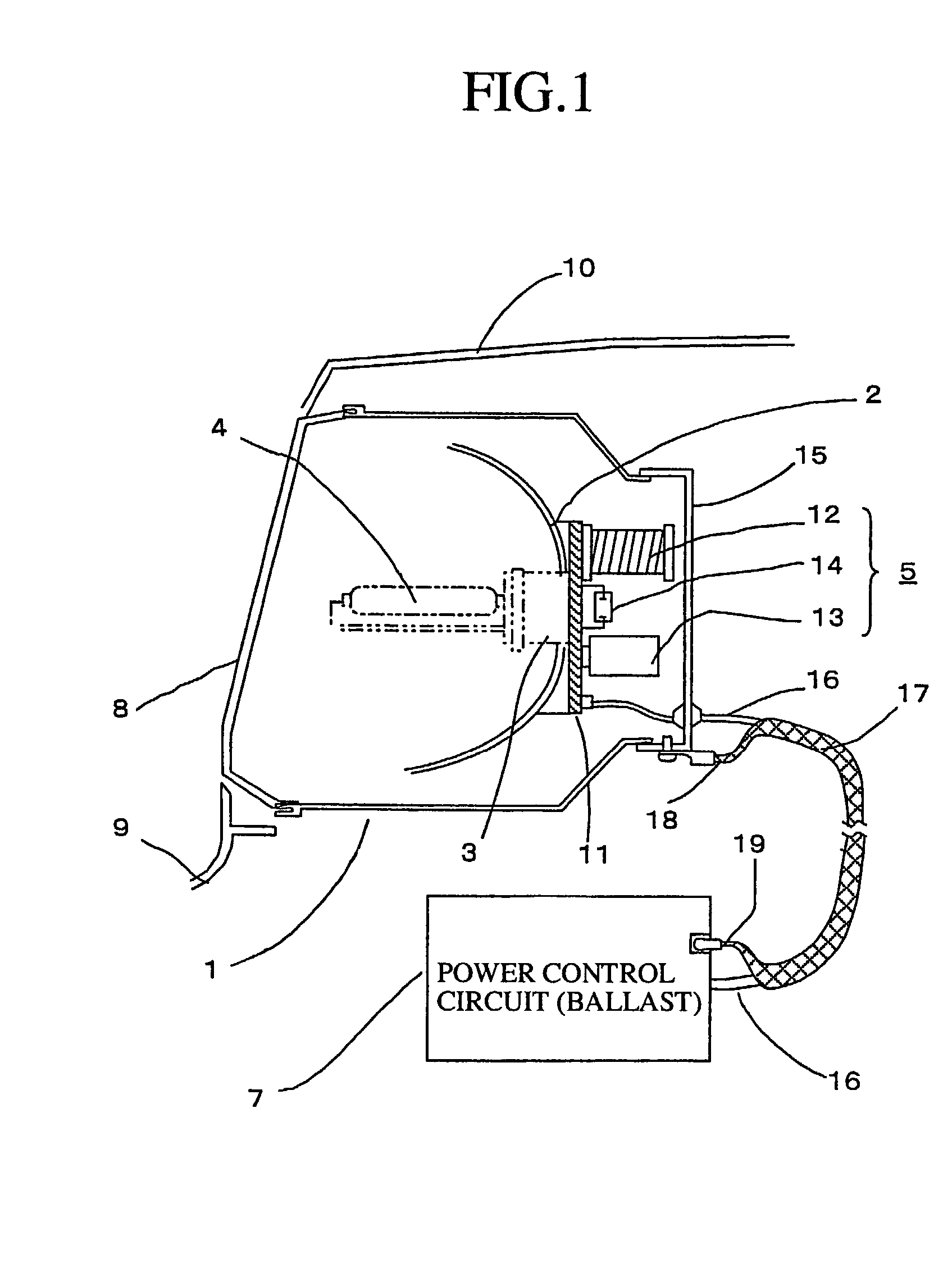
[0053]FIG. 3 is a perspective view showing an external view of a ballast and an ignitor-integrated type bulb socket in an HID lighting device for a motor vehicle, and FIG. 4 is a perspective view showing the harness thereof.

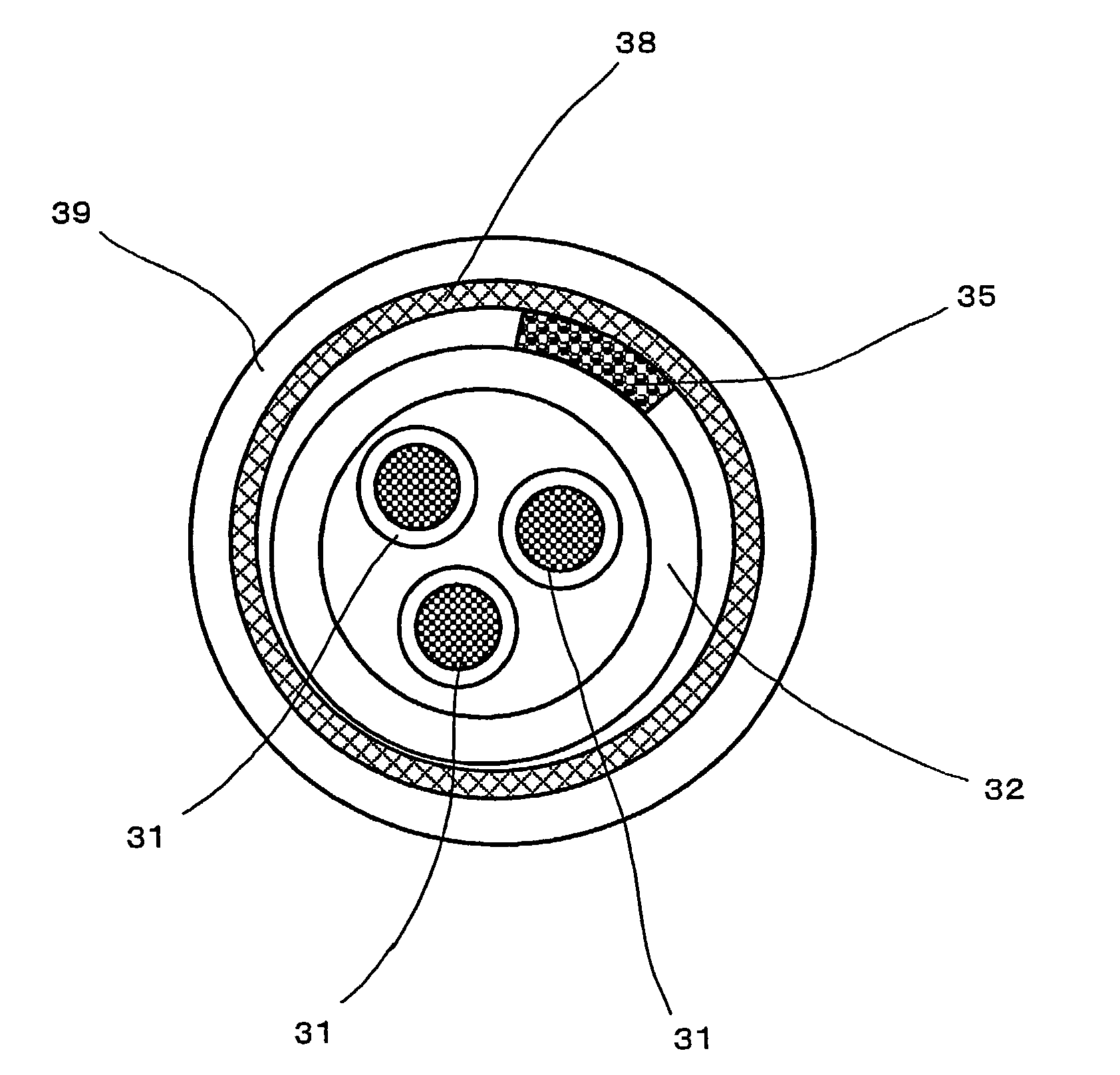
[0054]FIG. 5 shows an axial sectional view of the harness, and FIG. 6 is a sectional view taken along the line A—A in FIG. 5.

[0055]Referring to FIGS. 3, reference numeral 20 denotes a ballast containing therein a power source and a control circuit, reference numeral 21 an upper case of the ballast, reference numeral 22 a lower case of the ballast, reference numeral 23 a connector on the power source side for supplying a DC power source from an onboard battery (not shown) into the ballast 20, and reference numeral 24 a connector on the output side for supplying power to the lighting fixture. Reference numeral 25 denotes heat-radiating fins for falling do...

second embodiment

[0068]FIG. 7 is an axial sectional view explaining the electromagnetic wave shielding wire of the second embodiment of the invention. The same reference numerals as those in the above the first embodiment indicate the same components, and therefore descriptions thereof are omitted for brevity s sake.

[0069]Here, the difference from the above first embodiment is in that the lead wire 35 for connector connection runs along the outside of the cover shielding wire 38. In this manner, by providing the lead wire 35 for connector connection outside the cover shielding wire 38, the lead wire 35 for connector connection is attached in the last manufacturing step. In other words, the plurality of signal wires 31 bundled together by the cross-linking polymer tube 32 are laid along the inside of the cover shielding wire 38 and thereafter the lead wire 35 for connector connection is laid therealong and both ends thereof are fixed by heat-contraction tubes 39. Taking this kind of arrangement saves...

third embodiment

[0071]FIG. 8 is an axial sectional view explaining the electromagnetic wave shielding wire of the third embodiment of the invention. The reference numerals in FIG. 8 are the same as those described in the above the first embodiment, and therefore descriptions thereof are omitted for brevity s sake.

[0072]The difference from the above first and second embodiments is in that the lead wire 35 for connector connection is not a continuous wire extending to both ends but is divided on both sides.

[0073]Referring to FIG. 8, reference numeral 35a denotes a first lead wire for connector connection which is connected to the ballast 20 side and reference numeral 35b denotes a second lead wire for connector connection which is connected to the bulb socket 40 side. As described above, since lead wires 35a and 35b for connector connection are separately provided and the lengths of the lead wires 35a and 35b for connector connection are made long enough to secure the required area of contact with th...


PUM


Abstract

A shielding wire is provided with a first conductor, a shield for sheathing the first conductor through an insulating member, and a second conductor which is in contact with the shield. Therefore, a troublesome step of unknitting the braid of the shield is eliminated, and the work is done at a higher efficiency and the manufacturing cost is reduced.

Description

[0001]This application is a 371 of PCT / JP01 / 07097 Aug. 17, 2001.[0002]1. Technical Field[0003]This invention relates to a shielding wire which is used, e.g., for a headlight of a motor vehicle and for a discharge lamp used in an illumination lamp or a street light in an outdoor facility, a warehouse, a factory, or the like, and to a method of manufacturing the shielding wire, as well as to a lighting device for a discharge lamp using a shielding wire.[0004]2. Background Art[0005]Conventionally, a shielding wire having wound a copper foil or a copper wire around a wire has been used in a high-voltage harness, or the like, so as to shield electromagnetic noises produced from the harness.[0006]For example, as described in JP 289764 / 1998 A, as a method of connecting a shield layer of the shielding wire to a connector, it makes a custom of peeling off a terminal end of the shielding wire such that a conductor and a shield layer thereof are exposed, and of connecting respectively the cond...

Claims


Application Information

Patent Timeline
IPC IPC(8): H01B9/02H01B9/00F21V25/00F21V19/00F21S8/10H01R9/03
CPCB60Q1/0088B60Q1/0094F21S48/1186H01B9/028H01R9/032F21S48/1109F21V25/00F21W2101/02H01R24/562H01R2107/00F21S41/172F21S41/192F21W2107/10H01R13/65912
Inventor OHSAWA, TAKASHIMINAMI, FUMIHIROSEKIYA, MUTSUO
Owner MITSUBISHI ELECTRIC CORP
Why Eureka
Try Eureka