North-south pole determination for carrier injection sensorless position sensing systems

Active Publication Date: 2005-11-22
HAMILTON SUNDSTRAND CORP
View PDF14 Cites 69 Cited by
  • Summary
  • Abstract
  • Description
  • Claims
  • Application Information

AI Technical Summary

Benefits of technology

[0007]The saliency induced negative sequence current or potential waveforms caused by the carrier injection can only provide an estimate of twice the rotor electrical angle, that is, it determines the position of a pole, any pole, and not necessarily the north pole needed for proper motor operation. In order to determine true rotor position, some means must be provided to discriminate north from south. This means exists in the field current rectification provided by the rotating rectifier in the field circuit of the wound field syn

Problems solved by technology

At rotor standstill or low speed there is insufficient back electromotive force (EMF) generated in a dynamoelectric machine to enable an accurate estimate of rotor position using only passive measurement of terminal potentials and currents.
Although the CIS technique described in Jansen

Method used


Image

  • North-south pole determination for carrier injection sensorless position sensing systems
  • North-south pole determination for carrier injection sensorless position sensing systems
  • North-south pole determination for carrier injection sensorless position sensing systems

Examples


Embodiment Construction

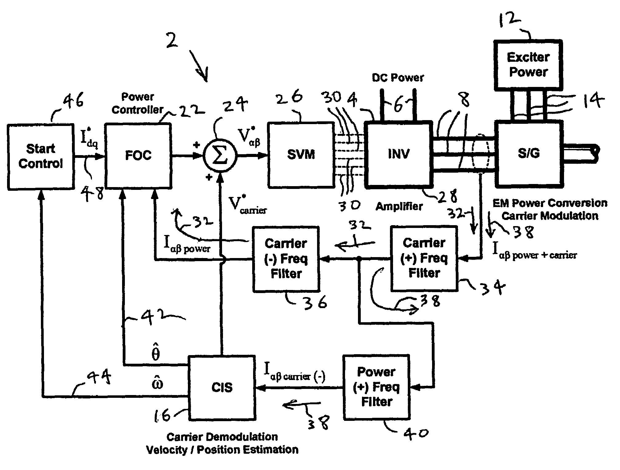
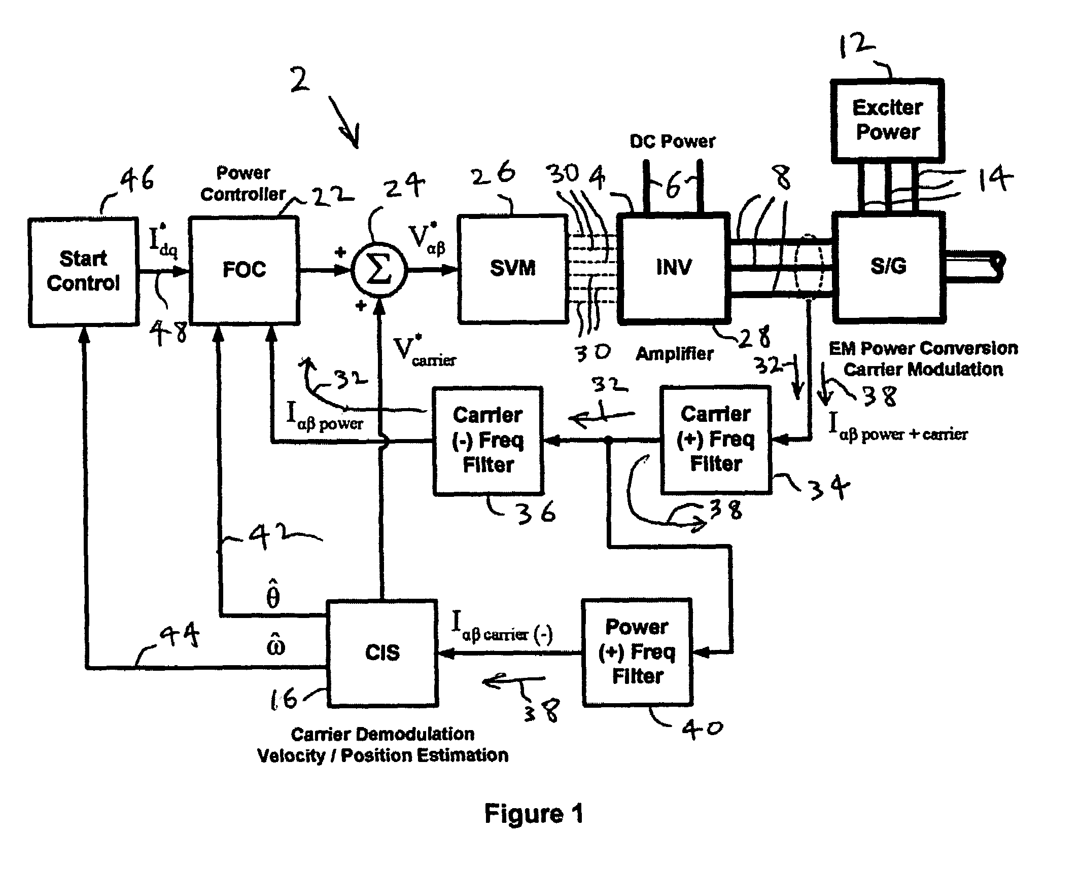
[0019]FIG. 1 shows a high level block diagram of a wound field synchronous machine control system that uses a CIS algorithm. Power processing blocks are shown in bold and signal processing blocks normal. A power inverter 4 converts direct current (DC) power provided on lines 6 to polyphase, typically three phase, alternating current (AC) power on lines 8 to drive a wound field synchronous machine 10, such as a motor or starter / generator. Exciter power for the machine 10 is provided by an excitation source 12 on lines 14. This diagram illustrates the use of carrier potential injection, although carrier current injection could also be used, and how the CIS algorithm fits nicely into the basic field oriented control (FOC) structure of modern motor control technology. A rotating carrier potential waveform generated by a CIS carrier demodulation and velocity / position estimation processor 16 on a signal path 18 is simply added by a summer 20 to potential commands generated by a FOC power ...


PUM


Abstract

A system for enhancing the performance of a carrier insertion sensorless (CIS) position sensing system for a wound field synchronous machine that utilises the positively rotating components (+2ωct) of the carrier second harmonic currents that contain rotor position information before field excitation to serve as a north-south pole indicator that determines if the CIS system has locked onto the north or south pole of the rotor.

Description

FIELD OF THE INVENTION[0001]The invention relates to rotor angular position and velocity sensing systems for dynamoelectric machines, and more particularly to an improved system for resolving the position of a rotor for a wound field synchronous machine using a carrier injection sensorless position sensing system at or near standstill.BACKGROUND OF THE INVENTION[0002]At rotor standstill or low speed there is insufficient back electromotive force (EMF) generated in a dynamoelectric machine to enable an accurate estimate of rotor position using only passive measurement of terminal potentials and currents. Some means must be provided to stimulate the machine in order to extract rotor position information. Many alternative schemes have been reported in the technical literature over the years.[0003]Stimulation can be applied to either the rotor or the stator, it can be either transient or continuous, and it may be of different frequencies. Nonetheless, all the reported approaches require...

Claims


Application Information

Patent Timeline
IPC IPC(8): H02P1/46H02P1/16H02P6/18H02P6/22
CPCH02P6/185H02P6/22
Inventor MARKUNAS, ALBERT L.DEFENBAUGH, JOHN F.HARKE, MICHAELROMENESKO, CHARLESSABAN, DANIEL M.
Owner HAMILTON SUNDSTRAND CORP
Why Eureka
Try Eureka