Storage battery charging station

a charging station and storage battery technology, applied in the direction of secondary cell charging/discharging, portable power-driven tools, electric vehicles, etc., can solve the problems of significant heat generation of the charging station's charging electronics, and achieve the effect of efficient cooling of the battery and the charging electronics

Inactive Publication Date: 2005-11-22
HILTI AG
View PDF10 Cites 26 Cited by
  • Summary
  • Abstract
  • Description
  • Claims
  • Application Information

AI Technical Summary

Benefits of technology

[0003]The object of the invention is to provide a process and a configuration for efficient cooling of the battery and the charging electronics.

Problems solved by technology

In addition, the charger electronics of the charging station also heat up significantly.

Method used


Image

  • Storage battery charging station
  • Storage battery charging station

Examples


Embodiment Construction

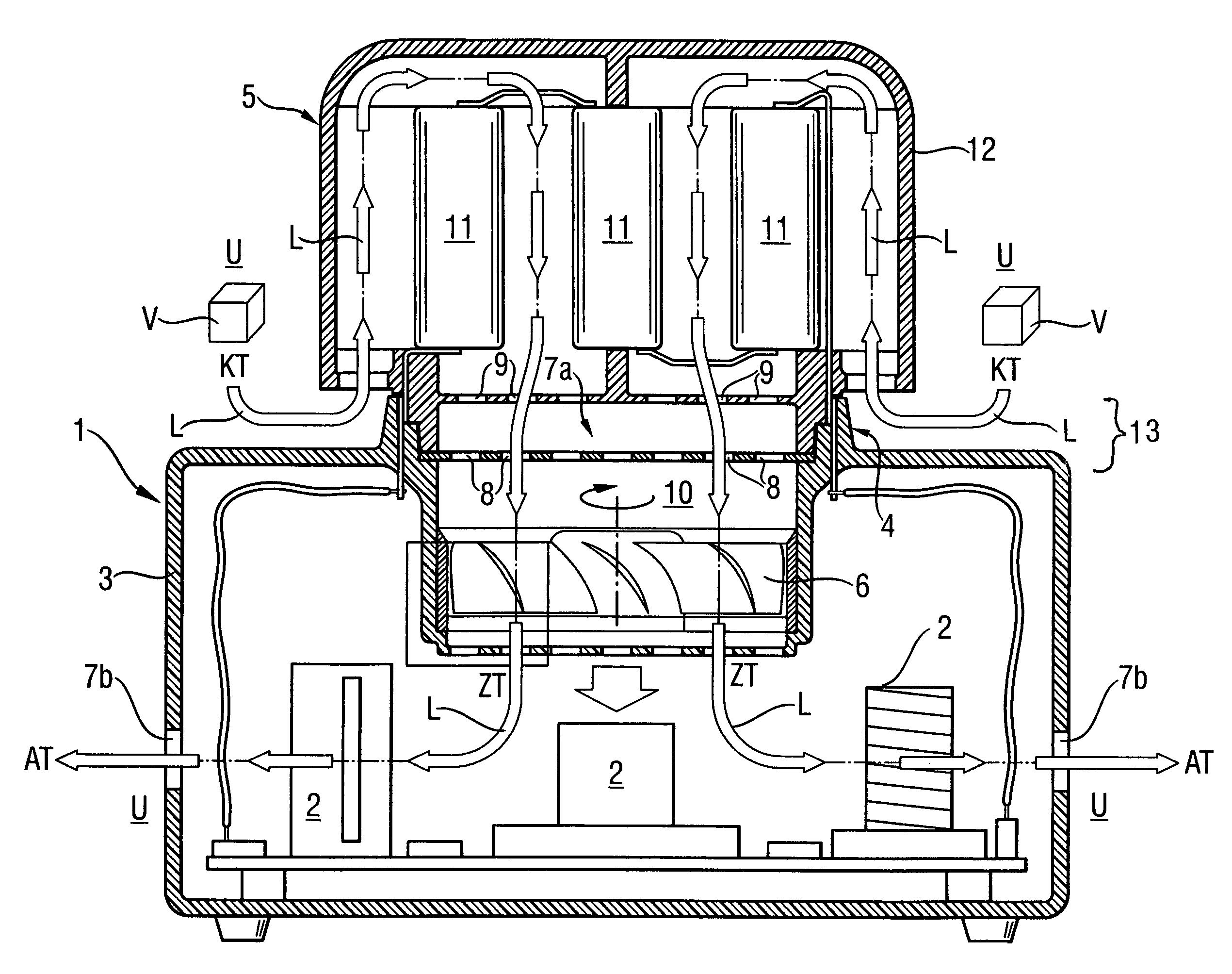
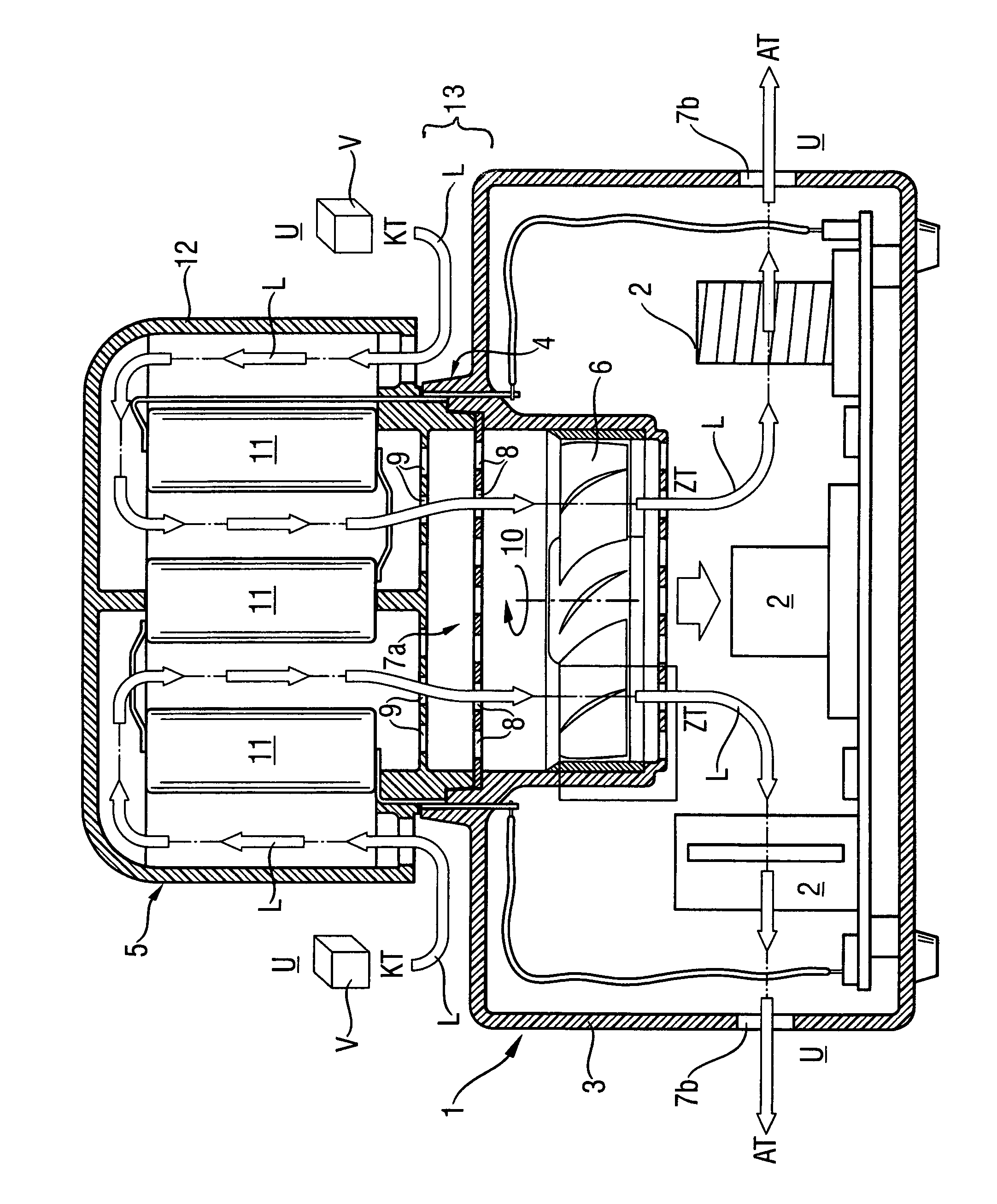
[0014]FIG. 1 shows a charging station 1 having a charging electronics 2 in a charger housing 3 that is physically and electrically connected to a rechargeable battery 5 (such as a storage battery module having a plurality of cells 11) by an electrical and physical contact interface 4. An air blower 6 is arranged in the charger housing 3. The blower 6 produces an air current L through two air vents 7a, 7b. The charger electronics 2 are arranged to transfer heat in the air current L.

[0015]The air vent 7a, on the flow inlet side, arranged in the upper section 13 of the charging station, is spatially associated with the physical contact interface 4 of the battery. The air blower 6 is arranged between the air vent 7a, on the flow inlet side, and the charging electronics 2. The air vent 7a on the flow inlet side has a plurality of surface-distributed air inlet points 8. Each surface-distributed air inlet point 8 is spatially associated with cooling vents 9 in the module housing 12 of the ...


PUM

PropertyMeasurementUnit
pressureaaaaaaaaaa
temperature CTaaaaaaaaaa
temperatureaaaaaaaaaa

Abstract

A charging station (1) for a rechargeable battery (5) that can be electrically and physically connected to the rechargeable battery (5). The charging station (1) has charger electronics (2) in a charger housing (3) and an electrical and physical contact interface (4) for the battery (5). An air blower (6) producing an air current (L) through two air vents (7a, 7b) is arranged in the charger housing (3). The air vent (7a) of the physical contact interface (4) is spatially associated with the battery (5) and the charger electronics (2) is arranged in the air current (L) to transfer heat. In the cooling process, in a first stage, an air volume (V) at cooling temperature CT is moved past the battery to transfer heat into and onto the battery and, in a second stage, the air volume (V) at an intermediate temperature IT>CT permeates the charger housing (2) containing the charging electronics (2.).

Description

BACKGROUND OF THE INVENTION[0001]The invention relates to a charging station for a rechargeable battery that is structurally and electrically compatible with the battery, such as a storage battery module for cordless hand tool machines. In modern rechargeable batteries, high energy densities can be charged in a brief period using a charging station, whereby the battery heats up significantly. In addition, the charger electronics of the charging station also heat up significantly. An important field of application of such high-density energy rechargeable batteries are storage battery modules for cordless hand tool machines such as screwing drills, combination hammers, hand circular saws, etc.[0002]EP 1178557 discloses a charging station for a rechargeable storage battery module of cordless hand tool machines that can be electrically and structurally connected to the module. The charging station has charging electronics, in a charger housing, with an electrical and structural contact ...

Claims


Application Information

Patent Timeline
Patent Type & Authority Patents(United States)
IPC IPC(8): H02J7/00B25F5/00H01M2/10H01M10/44H01M10/50
CPCH02J7/00H02J7/0042
Inventor HEIGL, BERNDZIEGLER, BERNDONTL, RAINER
Owner HILTI AG
Why Eureka
Try Eureka