Dynamically reconfigurable wire antennas

Inactive Publication Date: 2005-11-22
HARRIS CORP
View PDF9 Cites 19 Cited by
  • Summary
  • Abstract
  • Description
  • Claims
  • Application Information

AI Technical Summary

Benefits of technology

[0006]The invention concerns a dynamically reconfigurable antenna. The antenna includes at least one antenna radiating element that is at least partially comprised of a conductive fluid. A dielectric structure is provided which defines at least one cavity for constraining the conductive fluid. The antenna also includes a fluid con

Problems solved by technology

This results in an impedance mismatch to the feed line when the antenna is operated outside a relatively narrow operational bandwidth.
If the impedance of different parts of the circuit do not match, this can

Method used


Image

  • Dynamically reconfigurable wire antennas
  • Dynamically reconfigurable wire antennas
  • Dynamically reconfigurable wire antennas

Examples


Embodiment Construction

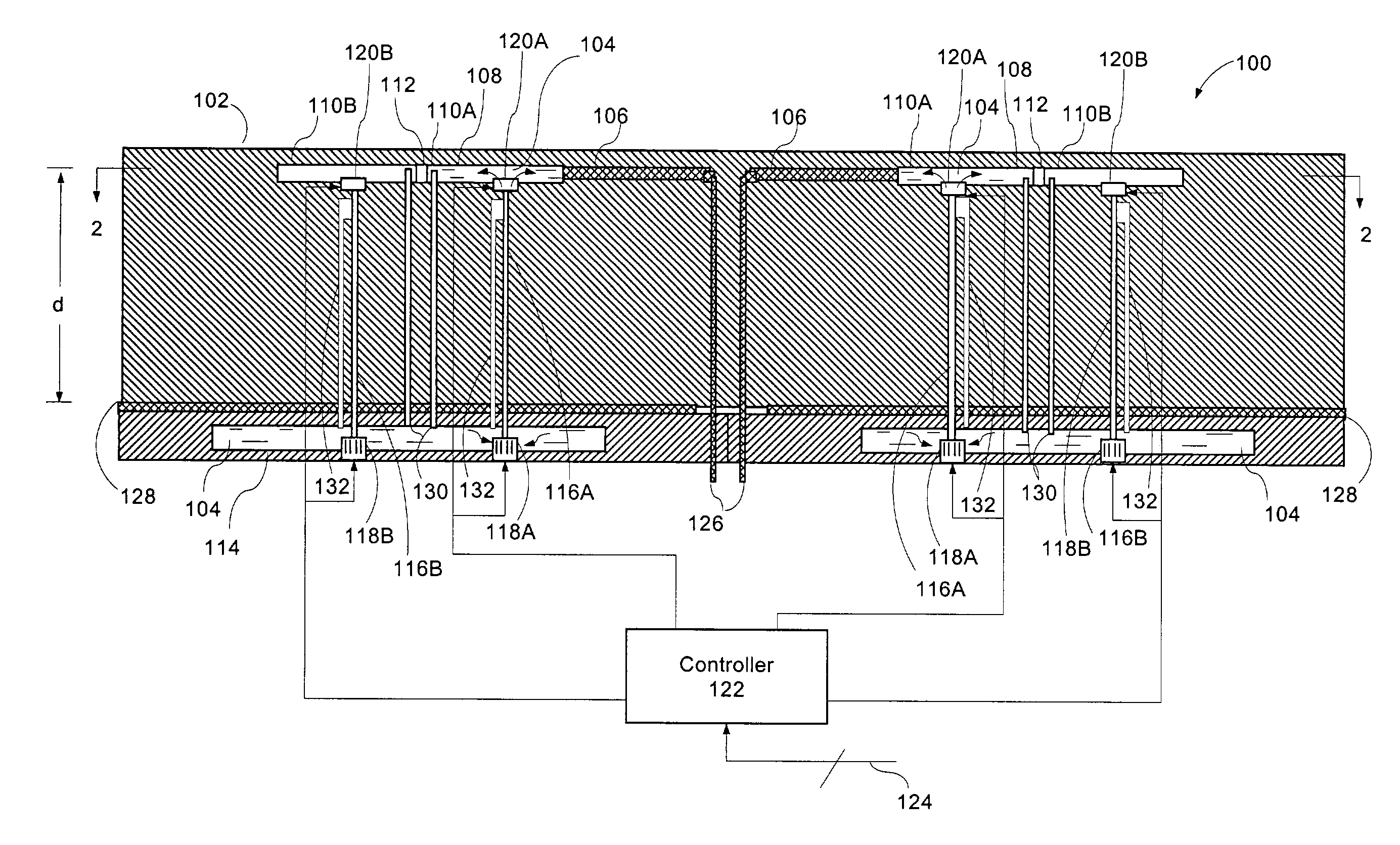
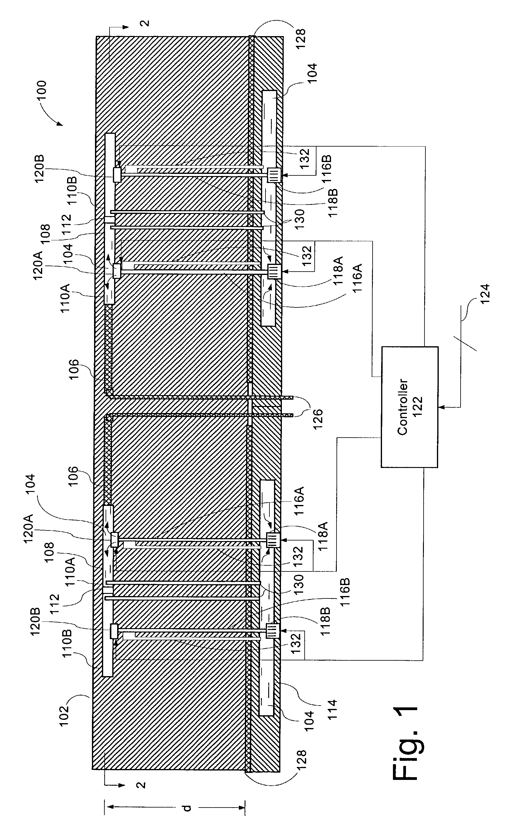
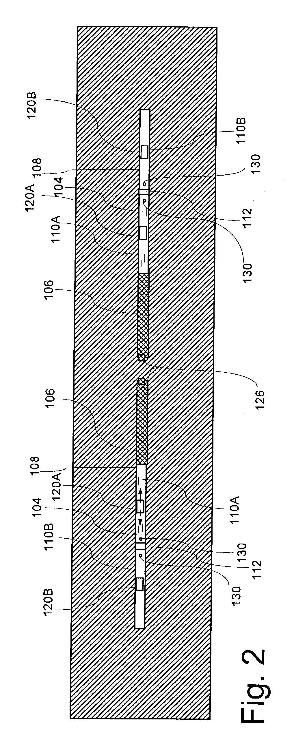
[0013]FIG. 1 is a cross-sectional view of an antenna 100 which is useful for understanding the invention. A further cross-sectional view of the antenna in FIG. 1, taken along line 2—2, is illustrated in FIG. 2. Antenna 100 can include one or more antenna radiating elements 108 that are at least partially comprised of a conductive fluid 104. A dielectric structure 102 is provided which defines at least one cavity 110A, 110B for constraining the conductive fluid 104. The antenna 100 also includes a fluid control system for selectively adding and removing the conductive fluid from the cavities 110A, 110B for controlling a dimension of the antenna radiating element. Suitable RF feed structure 126 can be provided for communicating an RF signal from a source to the antenna radiating elements 108.

[0014]The fluid control system can be comprised of a fluid reservoir 114, one or more pumps 118A, 118B, and fluid control valves 120A, 120B. The system can also include a controller 122 responsive...


PUM


Abstract

An antenna (100) includes an antenna radiating element (108) that is at least partially comprised of a conductive fluid (104). A dielectric structure (102) defines at least one cavity (110A, 110B) for constraining the conductive fluid. The antenna also includes a fluid control system (116A, 116B, 118A, 118B, 120A, 120B, 122) for selectively adding and removing the conductive fluid from the cavity for controlling a dimension of the antenna radiating element (108). The antenna radiating element (108) can be comprised of a plurality of cavities (110A, 110B), with each cavity defining a segment of the antenna radiating element (108).

Description

BACKGROUND OF THE INVENTION[0001]1. Statement of the Technical Field[0002]The inventive arrangements relate generally to methods and apparatus for multi-band antenna operation, and more particularly for dynamically changing the operational characteristics of an antenna.[0003]2. Description of the Related Art[0004]A wide variety of RF antenna elements are commonly manufactured on dielectric substrate. These include common dipole antenna elements as well as a variety of patch type antennas. The band of frequencies over which such antennas will function is largely determined by the geometry of the antenna element, ground plane spacing and characteristics of the dielectric substrate on which the antenna is formed. In many types of antenna element, antenna impedance changes significantly with frequency. This results in an impedance mismatch to the feed line when the antenna is operated outside a relatively narrow operational bandwidth. If the impedance of different parts of the circuit d...

Claims


Application Information

Patent Timeline
IPC IPC(8): H01Q5/00H01Q1/36H01Q5/02H01Q9/04H01Q9/16H01Q5/15
CPCH01Q1/364H01Q9/14H01Q9/16
Inventor RAWNICK, JAMES J.BROWN, STEPHEN B.
Owner HARRIS CORP
Why Eureka
Try Eureka