Electronic compass system
a compass and electronic technology, applied in the field of electronic compass, can solve the problems of unnecessary warranty claim, process time-consuming, and inability of the processing circuit to use a simple heading angle calculation to determine the appropriate heading
- Summary
- Abstract
- Description
- Claims
- Application Information
AI Technical Summary
Benefits of technology
Problems solved by technology
Method used
Image
Examples
first embodiment
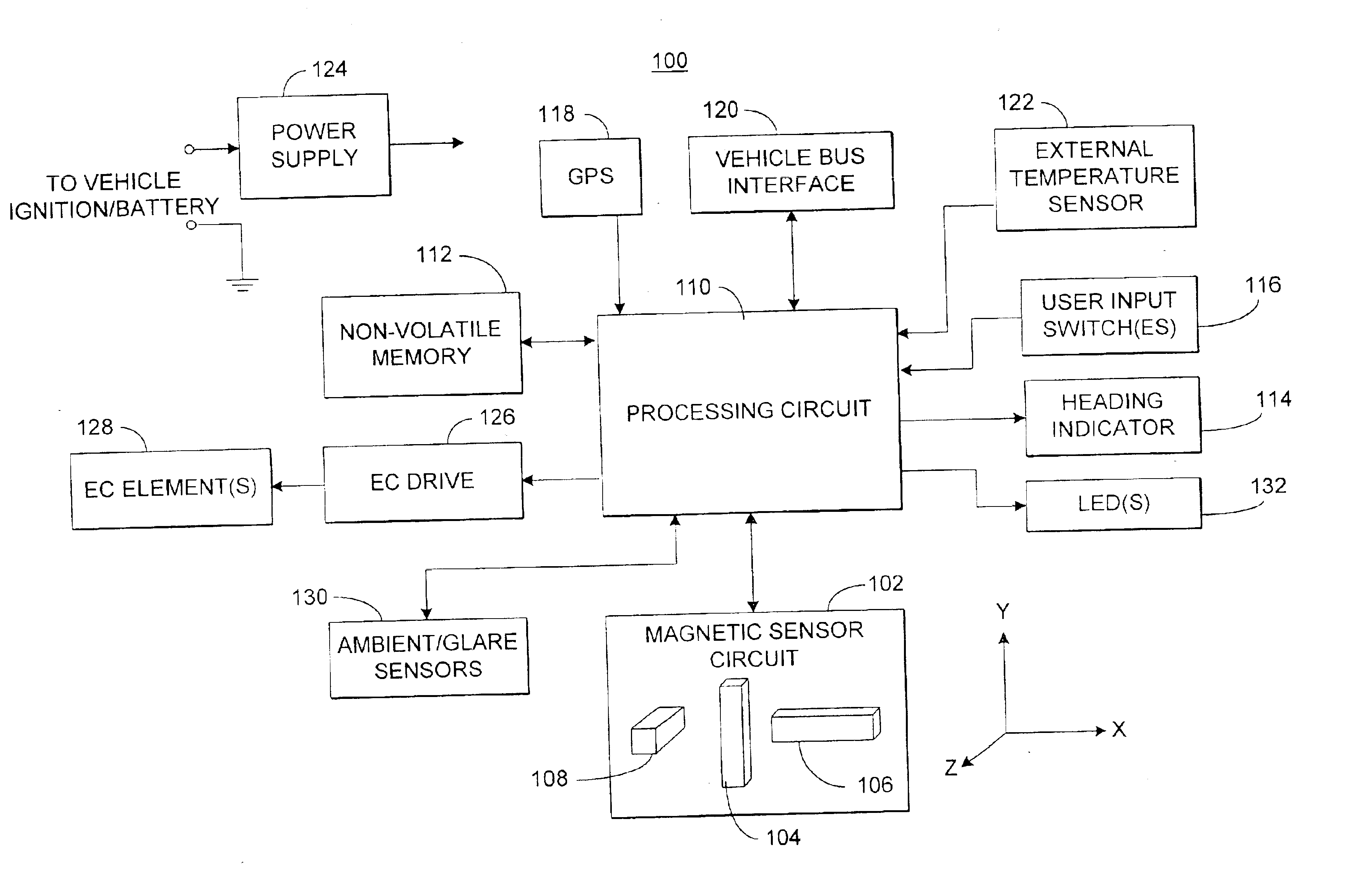
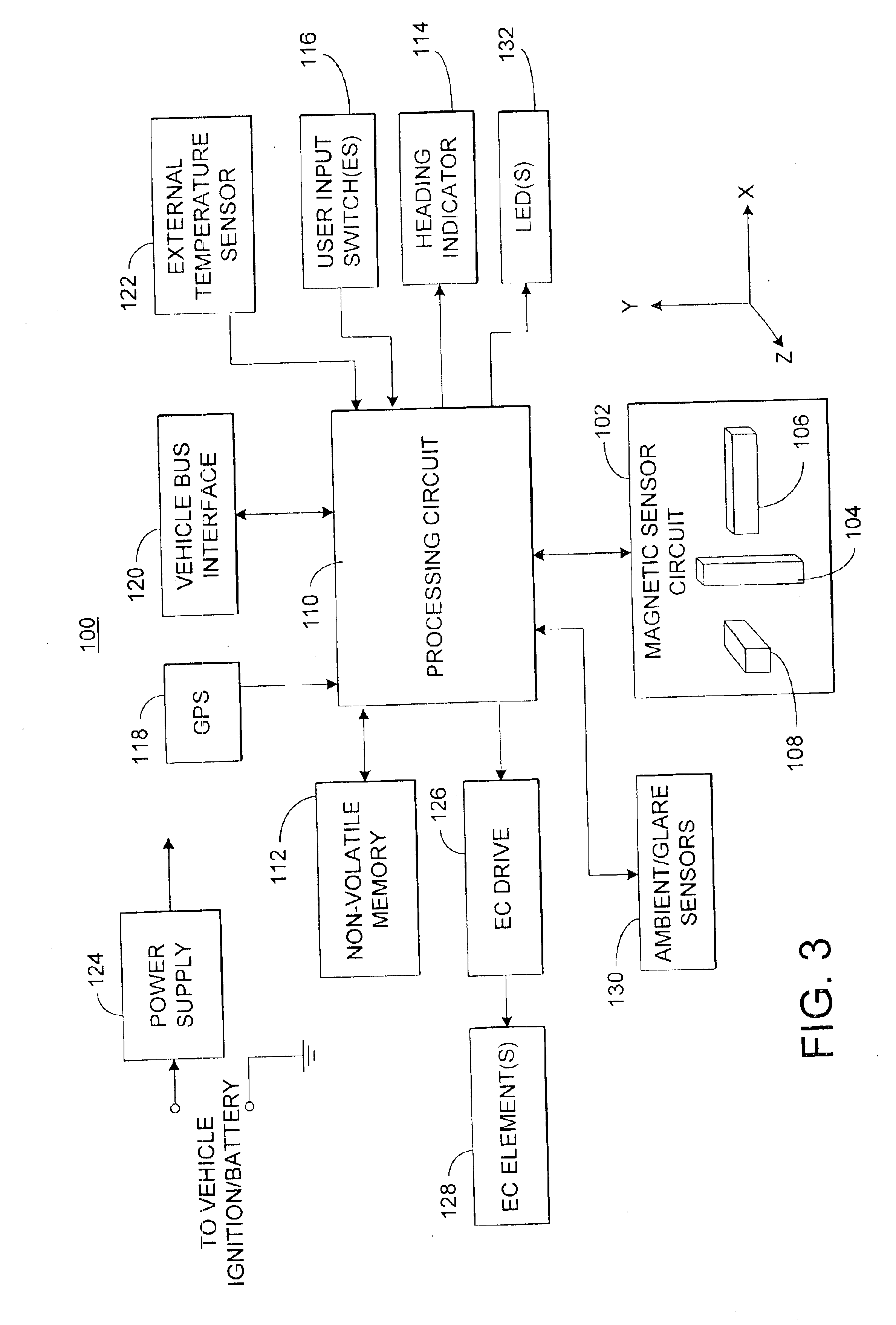
[0074]Having described the hardware for the electronic compass system, a general overview is provided below of the inventive process to be executed by processing circuit 110. Following the general overview, a detailed description of a first embodiment illustrating one implementation of some of the inventive concepts is provided with reference to FIGS. 11-21.
[0075]As noted above, in the preferred embodiments, the magnetic sensor circuit 102 includes a Z-axis sensing element 108 that is disposed substantially vertically to sense magnetic field components perpendicular to the components sensed by the X and Y axis sensors 104 and 106. Accordingly, the inventive process preferably maps the data in a three-dimensional coordinate system. Ideally, the mapped data would then correspond to a sphere rather than a circle in a single fixed plane.
[0076]To better illustrate the principles of the present invention, reference is now made to FIG. 8, which shows the coordinate system of the magnetic s...
second embodiment
[0158]The main process flow diagram for the specific example of the second embodiment is shown in FIG. 22A. The main process 500 begins with step 502, in which the hardware is initialized. This includes initialization of I / O, memory, the magnetometer, and the display. Then in step 504, processing circuit 110 of compass circuit 100 (FIG. 3) determines whether the data stored in the nonvolatile memory (NVM) 112 is valid. If not (as would be the case upon initial startup in a new vehicle), the process flows to the decalibrate subroutine 506, which is described in detail below with respect to FIG. 22B. Otherwise, if there is valid data in NVM 112, processing circuit 110 determines whether there are enough reference points accumulated and stored for a good calibration solution (e.g., four or more reference points). If not, the decalibrate subroutine 506 is executed. Otherwise, the process proceeds to step 510 in which event driven and background tasks are started. When the process return...
PUM
 Abstract
Description
Claims
Application Information
 - R&D
- Intellectual Property
- Life Sciences
- Materials
- Tech Scout
- Unparalleled Data Quality
- Higher Quality Content
- 60% Fewer Hallucinations
Browse by: Latest US Patents, China's latest patents, Technical Efficacy Thesaurus, Application Domain, Technology Topic, Popular Technical Reports.
© 2025 PatSnap. All rights reserved.Legal|Privacy policy|Modern Slavery Act Transparency Statement|Sitemap|About US| Contact US: help@patsnap.com


