Failure diagnostic device of evaporative gas purge control system

a technology of evaporative gas purge control and failure diagnosis, which is applied in the direction of electrical control, machines/engines, instruments, etc., can solve the problems of reducing the detection reducing the reducing the chance of failure diagnosis to check any closed sticking of the drain valve. , to achieve the effect of improving the determination accuracy of failure diagnosis, simple structure and enhancing product reliability

Inactive Publication Date: 2005-11-29
SUBARU CORP
View PDF4 Cites 16 Cited by
  • Summary
  • Abstract
  • Description
  • Claims
  • Application Information

AI Technical Summary

Benefits of technology

[0021]Accordingly, it is an object of the present invention to provide a failure diagnostic device of an evaporative gas purge control system for improving a determination accuracy of failure diagnosis with a simple structure without largely changing a structure of a pressure control valve, and enhancing a reliability of a product.

Problems solved by technology

On the other hand, when the drain valve is close-stuck, little differential pressure is caused between the fuel tank side and the canister side.
Further, the chances for the failure diagnosis to check any closed sticking of the drain valve are also reduced, and as the result, a detection accuracy of the failure diagnosis is degraded.

Method used


Image

  • Failure diagnostic device of evaporative gas purge control system
  • Failure diagnostic device of evaporative gas purge control system
  • Failure diagnostic device of evaporative gas purge control system

Examples


Embodiment Construction

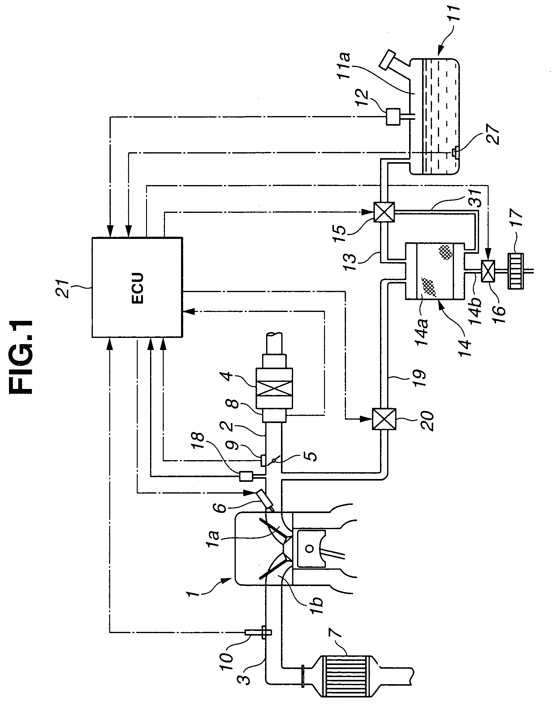
[0031]An embodiment of the present invention will be described below with reference to attached drawings. Reference numeral 1 in FIG. 1 denotes an engine, and an air intake passage 2 and an exhaust passage 3 are communicated with an intake port 1a and an exhaust port 1b of this engine 1, respectively. An air cleaner 4 is disposed on the upstream side of the air intake passage 2, a throttle valve 5 is disposed on the downstream side thereof, and a fuel injector 6 is disposed immediately on the upstream side of an intake port 1a. In addition, a catalyst 7 is interposed in the middle of the exhaust passage 3, and communicated with an exhaust muffler (not shown). Reference numerals 8, 9 and 10 denote an air flow sensor, a throttle opening sensor, and an oxygen sensor to detect the oxygen concentration in an exhaust gas, respectively.

[0032]Reference numeral 11 denotes a fuel tank, a fuel stored in this fuel tank 11 is communicated with the fuel injector 6 via a fuel passage (not shown), ...


PUM


Abstract

A state of an energization of a normal open type drain valve interposed between a fresh air introducing port of a canister and a drain filter is checked. And if the valve is not the energized state (open state), the tank internal pressure is checked. If the tank internal pressure is lower than a predetermined value and the state is maintained for a predetermined time, it is determined that the drain valve is close-stuck. If the drain valve is close-stuck, the pressure in the canister becomes negative, and the negative pressure is introduced in a fuel tank via a passage to an atmosphere and a pressure control valve. Closed sticking of the drain valve can be detected by checking the tank internal pressure.

Description

[0001]The disclosure of Japanese Patent Application No. 2003-061956 filed on Mar. 7, 2003 including the specification, drawings and abstract is incorporated herein by reference in its entirety.BACKGROUND OF THE INVENTION[0002]1. Field of the Invention[0003]The present invention relates to a failure diagnostic device of an evaporative gas purge control system for diagnosing a presence of a drain valve sticking provided in a fresh air line to a canister.[0004]2. Description of the Related Art[0005]Some engines for vehicles have been provided with an evaporative gas purge control system to feed (or return) an evaporative fuel to an engine intake system and burn thereof in order to prevent an evaporative fuel gas generated in a fuel tank from leaking outside.[0006]Such a kind of the evaporative gas purge control system like this comprises a canister to adsorb the evaporative fuel, an evaporative gas passage to communicate the canister with the fuel tank, and a purge passage to communica...

Claims


Application Information

Patent Timeline
Patent Type & Authority Patents(United States)
IPC IPC(8): F02D41/00F02D41/22F02M25/08
CPCF02M25/0809F02M2025/0845
Inventor NAKOJI, YASUSHI
Owner SUBARU CORP
Why Eureka
Try Eureka