Smooth rolling cover crop roller

a crop roller and smooth rolling technology, applied in the field of smooth rolling cover crop roller, can solve problems such as plant death

Inactive Publication Date: 2005-11-29
AGRI UNITED STATES OF AMERICA REPRESENTED BY THE SEC OF THE +1
View PDF13 Cites 68 Cited by
  • Summary
  • Abstract
  • Description
  • Claims
  • Application Information

AI Technical Summary

Benefits of technology

[0012]Another object of this invention to provide an improved apparatus and method for rolling and crimping cover crops without excessive vibration as the apparatus is rolled across a field at a relatively high speed.

Problems solved by technology

During use, as the apparatus is rolled across a field having a crop thereon, the blades contact and crimp the stalks of the crop, effectively causing the plants to die.

Method used


Image

  • Smooth rolling cover crop roller
  • Smooth rolling cover crop roller
  • Smooth rolling cover crop roller

Examples


example 1

[0037]To enhance our understanding of the rolling / crimping process, a series of three experiments were carried out. For the first experiment, an existing prototype roller was used. This roller was a small section of a three-piece roller assembly constructed by Bigham Brothers, Inc. (Lubbock, Tex.). The small roller (1.14 m width×0.41 m diameter) was removed from the larger implement and placed on a category 1 toolbar (ASAE, 1998). A weight bracket was added to the implement so that the amount of weight could be varied.

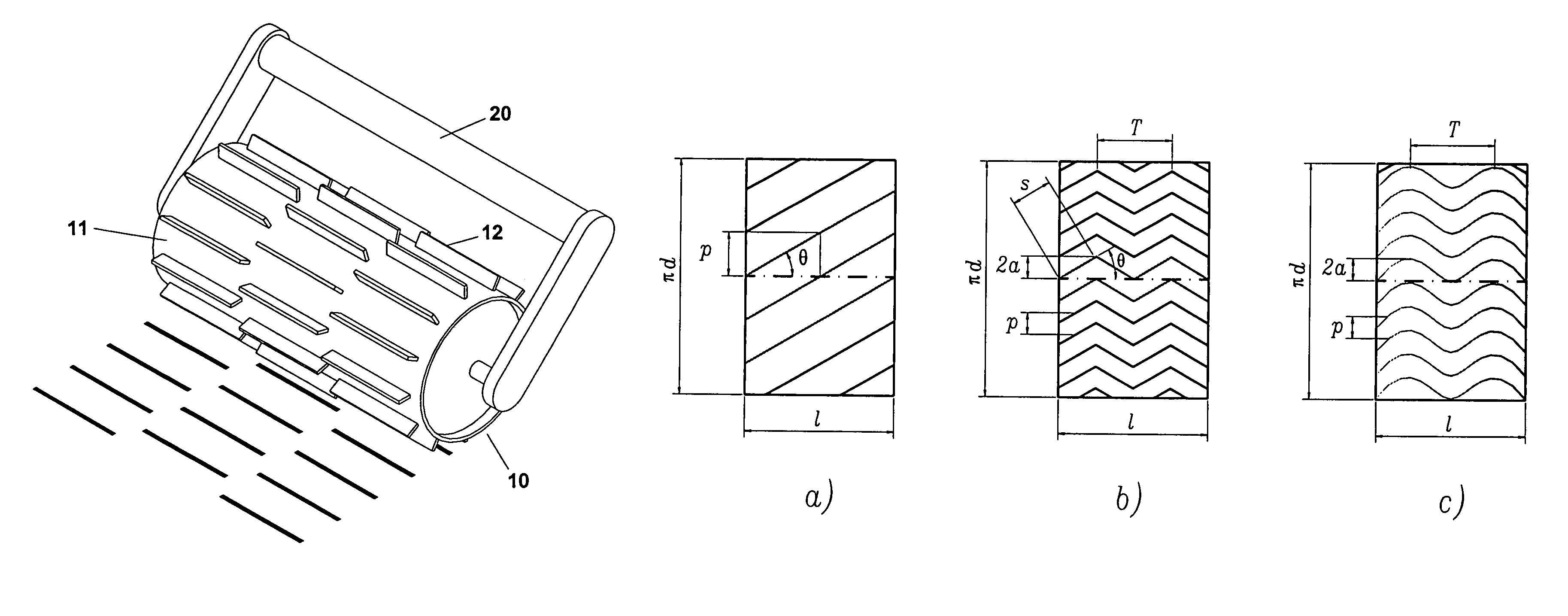
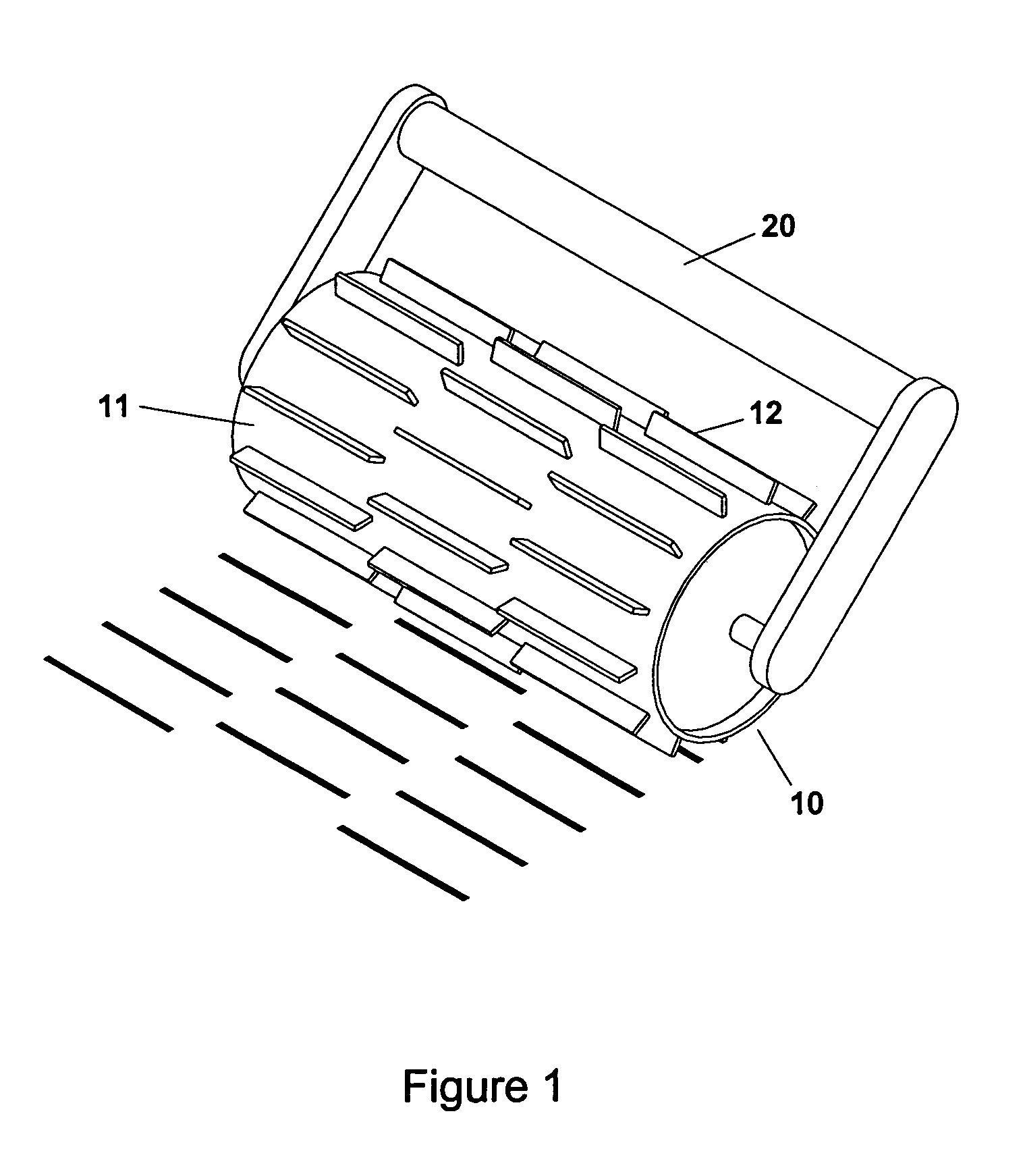
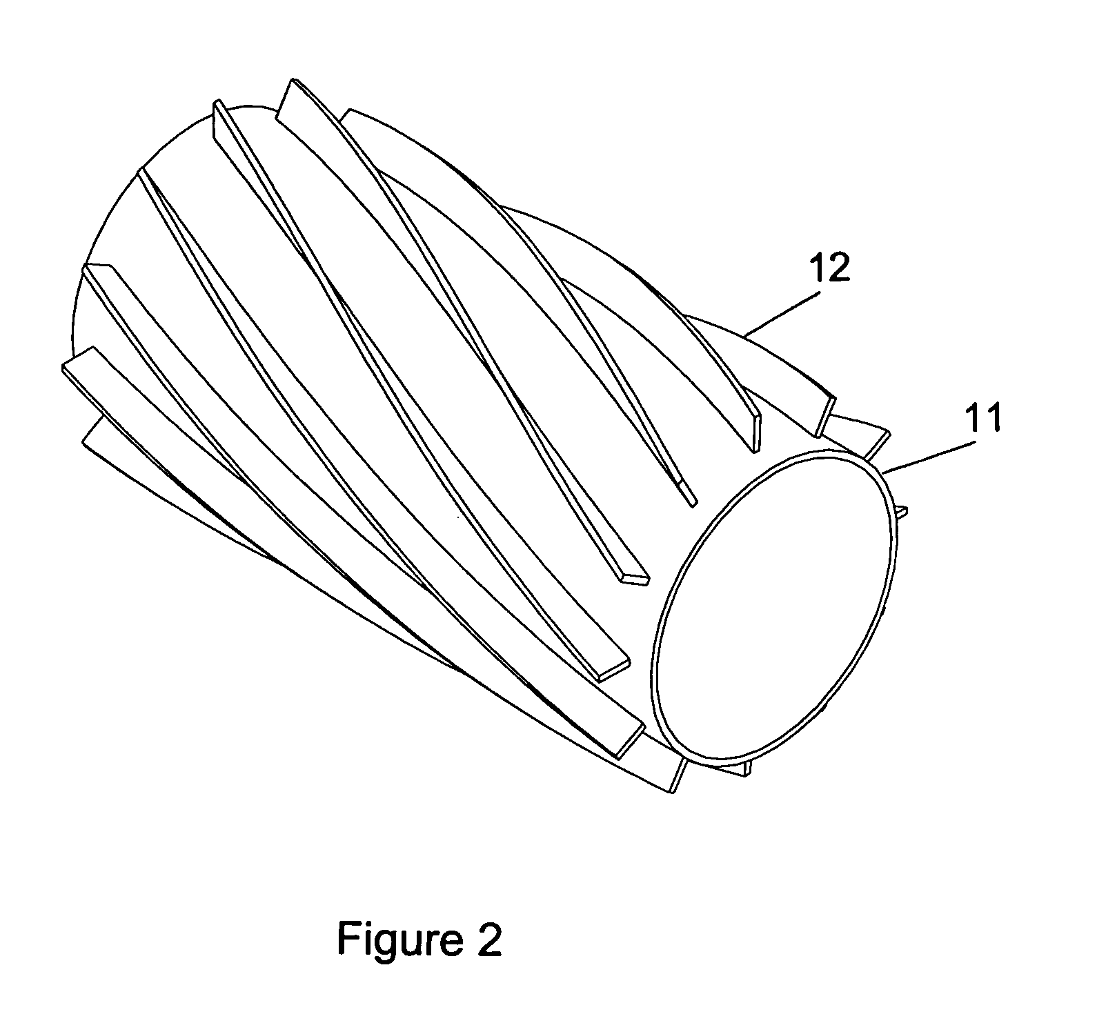
[0038]The blades on the roller were straight blades of 6.4 mm thickness and 0.10 m height extending across the full length of the roller drum, and were rigidly attached to the roller drum at seven different locations around the drum with a uniform circumferential spacing of 0.18 m. These blades were blunt and were not designed to cut the cover crop, rather they were designed to crimp it and leave it intact. Between the blades, 8.8 cm angle iron was welded onto the roll...

example 2

[0050]A second experiment was conducted to evaluate different blade systems in soil bins. For both the second and third experiments, an experimental roller was designed and manufactured that had the capability of using three different blade systems described below. This implement had a diameter of 0.41 m, a width of 0.91 m, and weighed 341 kg. It was mounted on a category 1 toolbar. This toolbar was mounted on a soil bin car which allowed only the roller to touch the cover crop or soil. The roller was operated at a speed of approximately 1.3 m / s.

[0051]The second experiment consisted of evaluating three different blade types and determining their different vibration characteristics and their crimping capability. The blades were all of 5 cm height and 6.4 mm thickness. This experiment was also conducted in the two outdoor soil bins of the NSDL in a Vaiden silty clay soil and a Hiwassee sandy loam soil.

[0052]To expedite the experiments, a sorghum-sudan grass (Sorghum bicolor, (L.) Moen...

example 3

[0059]The third experiment was conducted to evaluate the different blade systems in the field. This experiment was conducted in the field on a Compass sandy loam soil (thermic Plintic Paleudults) and in a concrete-floored shed at the E. V. Smith Research Station near Shorter, Ala. The experiment consisted of determining vibration information for each of the three blade systems used on the experimental roller used in Experiment 2. These blade systems were: (1) long-straight blades, (2) short-staggered straight blades, and (3) curved blades. Four replications of each blade treatment were conducted on three surfaces: (1) rye cover crop in field, (2) grassed area, and (3) concrete shed floor. The small roller was attached to the JD 4400 tractor and was operated at a constant speed of approximately 1.3 m / s.

[0060]A rye cover crop was grown during winter months of 2002 and spring months of 2003. The experiment was conducted in late April 2003 when the rye cover crop was in a late soft doug...


PUM


Abstract

Cover crops may be rolled and crimped using an apparatus which may be rolled across a field at a relatively high speed without excessive vibration. The apparatus includes a substantially cylindrical drum which has a plurality of rows of outwardly extending blades projecting therefrom. The blades may be wave-shaped, curved, substantially straight and discontinuous, blades paired with a plurality of spaced apart outwardly extending rings, or combinations thereof. In use as the apparatus is rolled across a field having a crop thereon, the blades contact and crimp the stalks of the crop, effectively killing the plant.

Description

BACKGROUND OF THE INVENTION[0001]1. Field of the Invention[0002]The invention relates to a novel apparatus and method for killing a cover crop by rolling and crimping.[0003]2. Description of the Prior Art[0004]Between 1990 and 2002, the number of U.S. cropland acres planted without tillage increased from 73.2 million acres to 103.1 million acres (CTIC, 2003). The use of cover crops has contributed to the overall success of conservation systems for many producers. Cover crops are increasingly being used to protect the soil from erosion during winter months, to enhance filtration and storage of winter rainfall, and reduce the negative effects of soil compaction (Reeves, 1994; Raper et al., 2000a; Raper et al., 2000b). Cover crops also increase the buildup of organic matter in the soil which leads to improved soil structure.[0005]In this practice, the cover crop should be terminated prior to planting the cash crop to prevent the cover crop from using valuable spring moisture that could...

Claims


Application Information

Patent Timeline
Patent Type & Authority Patents(United States)
IPC IPC(8): A01B29/04A01B49/04
CPCA01B29/045
Inventor RAPER, RANDY L.SIMIONESCU, PETRU-AURELIAN
Owner AGRI UNITED STATES OF AMERICA REPRESENTED BY THE SEC OF THE
Why Eureka
Try Eureka